Parts and functions installations, Step1, Step2 – i-PRO WV-QJB502 Ceiling Surface Mount Bracket (White) User Manual
Page 2: Step3, Step4, Step5, Step6
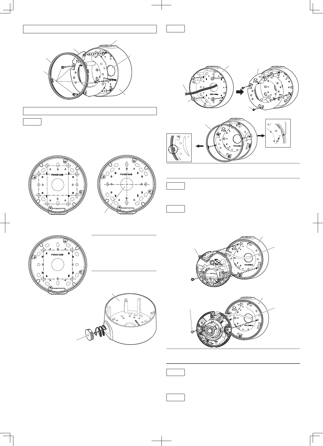
Parts and functions
Installations
Step1
Make a hole on the installation surface.
[1]
Make screw holes or anchor holes in the ceiling or wall, and also cable access hole if
necessary.
No cable access hole is needed when using conduit.
Attachment plate
(accessory)
Fixing screw for
attachment plate
(4pcs.)
(M3×10 mm {13/32
inches}: accessory)
Conduit wiring connector
Cable access hole
Base bracket
Note:
• When mounting to a single-gang junction
box, fix it with screws (2 pcs.) (M4: locally
procured).
• The direction of the attachment plate
(installation direction of the camera) can
be changed with steps of 90° even after
the base bracket is fixed.
83.5 mm × 46 mm
{3-9/32 inches × 1-13/16 inches}/
82.5 mm × 47.6 mm
{3-1/4 inches × 1-7/8 inches}
83.5 mm {3-9/32 inches}/
83.3 mm {3-9/32 inches}
63 mm {2-15/32 inches}/
63 mm {2-15/32 inches}
Cable access hole
ø25.4 mm {ø1 inch}
[2]
Remove the cap for the female thread for the
conduit using a 5 mm {3/16 inches} hexagon
wrench and attach the conduit.
The female thread for conduit is compliant
with ANSI NPSM (parallel pipe threads) 3/4 or
ISO 228-1 (parallel pipe threads) G3/4.
Step2
Fix the base bracket and install the attachment plate and cover in
the direction described in [2] of “Preparations”.
[1]
Install the base bracket on the installation surface.
Fixing screws (4 pcs.) (M4: locally procured)
Minimum pull-out strength: 196 N {44 lbf} (per 1 pc.)
[2]
Install the attachment plate onto the base bracket and then attach the cover to the
attachment plate. The following is an example when this bracket is installed on the wall.
(Recommended tightening torque: 0.69 N·m {0.51 lbf·ft})
Base bracket
Cap for the female thread for
the conduit
Note:
• When installing this bracket outdoors, be sure to apply waterproofing to the cable access
hole and fixing screw holes.
A
Cable
Fixing screw (4 pcs.)
(M4: locally procured)
Fixing screw for
attachment plate
(4 pcs.)
(M3×10 mm {13/32
inches}: accessory)
Attachment plate
Base bracket
Step3
Connect the cables to the camera.
Connect an Ethernet cable to the RJ45 network cable from the camera.
Refer to the Installation Guide of the camera for how to install the waterproof connector.
Step4
Fix the camera body to this bracket.
(Recommended tightening torque: 1.37 N·m {1.01 lbf·ft})
Cable
Fixing screw for camera (3 pcs.)
(M4×10 mm {13/32 inches}: accessory)
Cable
Base bracket
Base bracket
Fixing screw for camera (2 pcs.)
(M4×10 mm {13/32 inches}: accessory)
Note:
• When fixing the camera on this bracket, be careful not to pinch the cable with this bracket
and damage the cable sheath.
Step5
Adjust the angle of view of the camera.
Turn on the power of the camera and adjust the angular field of view of the camera.
Refer to the Installation Guide of the corresponding camera for how to connect to a network and
for how to adjust the angle of view of the camera.
Step6
Attach the enclosure.
After finishing the adjustment, attach the enclosure by following the instructions in the Installation
Guide of the corresponding camera.
Refer to the Installation Guide of the corresponding camera for the recommended tightening
torque to be applied when fixing the enclosure of the camera.
Cover
(accessory)
Cover
(accessory)
Flat portion
Mark