Rear panel features, Rear panel features 4, Chapter 1 – Lanner LEC-3110 User Manual
Page 6: Introduction
4
Introduction
Chapter 1
Embedded and Industrial Computing
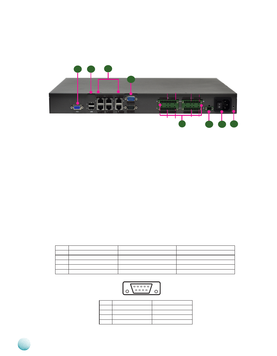
Rear Panel Features
R1 VGA Connector
The VGA is provided by the integrated GPU which implements Intel® Graphics Media Accelerator 3150
R2 Two USB 2 0 type A ports
It connects to any USB devices, for example, a flash drive There is another external port on the front panel
and one internal USB dip connector on the mainboard They all have ESD Protection of 15KV
R3 6 Gigabit Ethernet LAN ports
LAN 1-6 are provided by Intel 82574L Ethernet controller which supports10/100/1000Mbps connection
speeds In addition, LAN1 and LAN2 Support Wake-on-LAN (WOL) and Preboot eXecution Environment
(PXE)
Using suitable RJ-45 cable, you can connect LEC-3110 System to a computer, or to any other piece of
equipment that has an Ethernet connection such as a hub or a switch
R4 Two RS-232 Serial Port (Bottom: COM1, Upper: COM2, fully compliant to RS-232 standard)
These two serial ports have default operation mode of RS-232 communication channel, but can be configured
as either RS-422 or RS-485 serial communication channel through dip switch selection Refer to Chapter 3
Motherboard Information for dip switch information They are capable of 15KV ESD (ElectroStatic Discharge)
Protection and 2KV Surge Digital Isolation
R5 20-pin Phoenix Contact Terminal Block
R6
R5
R2
R1
R4
Pin 1
Pin 1
Pin 1 Pin 1
R3
LAN1 LAN3 LAN5
LAN2 LAN4 LAN6
COM3 COM5
COM1
COM2
COM4 COM6
COM8 COM10
COM7 COM9
Pin 1 Pin 1
Pin 1 Pin 1
Pin No.
Pin name for RS-232
Pin name for RS-485/RS-422
Pin name for RS-485(2 wires)
1
Data Carrier Detect (DCD)
TXD-
DATA-
2
Received Data (RXD)
TXD+
DATA+
3
Transmitted Data (TXD)
RXD+
4
Data Terminal Ready (DTR)
RXD-
5
Signal Ground (GND)
Ground (GND)
Pin No.
Pin name for RS-232
Pin name for RS-485
6
Data Set Ready (DSR)
7
Request to Send (RTS)
8
Clear to Send (CTS)
9
Ring Indicator (RI)
6 7 8 9
1 2 3 4 5
R7
R8