Vi. installation and connection – ARM Electronics SDKBD2&3 User Manual
Page 9
1
Back Light Compensation
ON
OFF
2 Zero
Illumination
ON
OFF
3 Display
ON
OFF
4 Digital
Zoom
ON
OFF
5
Back Light of Keyboard Screen
ON
OFF
6 Focus
Automatic
Manual
7 Iris
Automatic
Manual
8 Automatic
Manual
9
Indoor Mode
Outdoor Mode
10
White Balance Mode(WB)
ATW Mode
One Push WB
11
Black & White/Color Switching
Color
Black & White
12
< 180°, low speed
> 180°, low speed
13
< 180°, middle speed > 180°, middle speed
14
Set Auto Pan (Only conditions for scan. If
start scan, operate as Item 9 in this
paragraph)
< 180°, high speed
> 180°, high speed
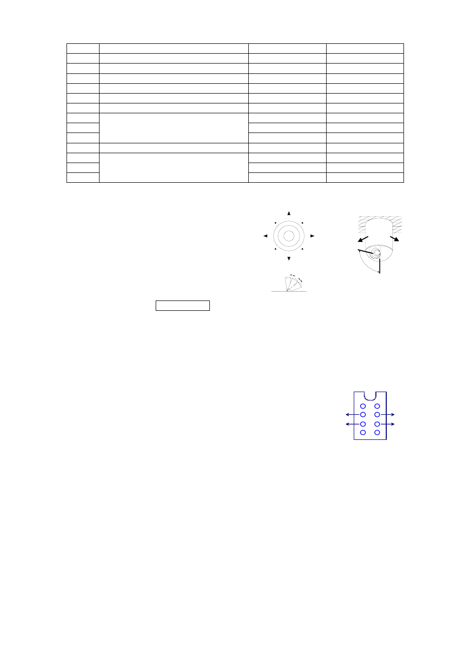
15. Use the Joystick to control the speed dome camera:
You can use the speed joystick to control the
Pan/Tilt direction and speed of the speed dome
randomly. The speed of pan/tilt is decided by the
angle of the joystick you operated (Figure 3).
Change the tilting angle of the joystick you can
adjust the speed evenly and the camera can be
focused automatically in the course of scan to
keep images being distinct.
16. In case error operation occurs, normal display
will be recovered after “Error Operation” appears
for 1 second.
VI. Installation and Connection:
Attention: Please read the operation manual of the keyboard and the speed dome carefully before connecting
wires. Any incorrect connections can cause permanent damage of the device. When connecting wires, first switch
off the power supply of all devices. The communication wires between devices should be shielded twisted cable.
When installing cables they should be far away from high voltage lines or other
possible interference circuits as can as possible.
1. The marking of wires of the transfer box (Figure 4)
2. Connections of the keyboard controller controlling multiple speed dome `
cameras (Figure 5)
3. Connections between the keyboard and the speed dome camera (Figure 6)
4. Connection Drawing between the keyboard and the multiplexer via the
address box (Figure 7)
5. System Connection Drawing between the keyboard and the dome camera
and the multiplexer (Figure 8)
RED
BLACK
GREEN
YELLOW
REDㄩRS485+
BLACKㄩRS485-
GREENㄩGND
YELLOWㄩRS232 OUT
Figure 4
Figure 3
UP
DOWN
RIGHT
LEFT
FAST
SLOW
LEFT
RIGHT
UP
DOWN