Pin assignment – ARM Electronics C4TMX User Manual
Page 11
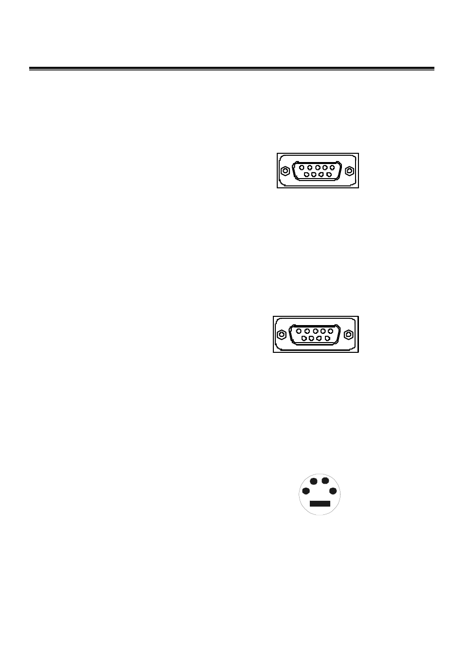
Pin Assignment
1~4 : Alarm Input CH1~CH4
5 : VCR Trigger
6 : GND
7 : Alarm Output NC
8 : Alarm Output COM
9 : Alarm Output NO
ALARM PORT ( DB-9 Female)
RS-232 PORT (DB-9 Female)
1 : Reserved
2 : RXD
3 : TXD
4 : Reserved
5 : GND
6 : Reserved
7 : Reserved
8 : Reserved
9 : Reserved
S-VHS PORT
1 : GND
2 : GND
3 : Y
4 : C
5 4 3 2 1
3
2
4
1
9 8 7 6
9 8 7 6
5 4 3 2 1
9