7 7 sae j1939 interface, 1 overview and structure of the sae j1939 protocol, 1 pdu format 1 – ifm electronic JN2301 User Manual
Page 7: 2 pdu format 2
UK
Inclination sensor JN
7
7 7 SAE J1939 interface
The inclination sensors have a standardised SAEJ1939 interface� All measured
values and parameter groups can be accessed via the J1939 protocol� The
individual configuration can be saved in the internal permanent memory (flash)�
7.1 Overview and structure of the SAE J1939 protocol
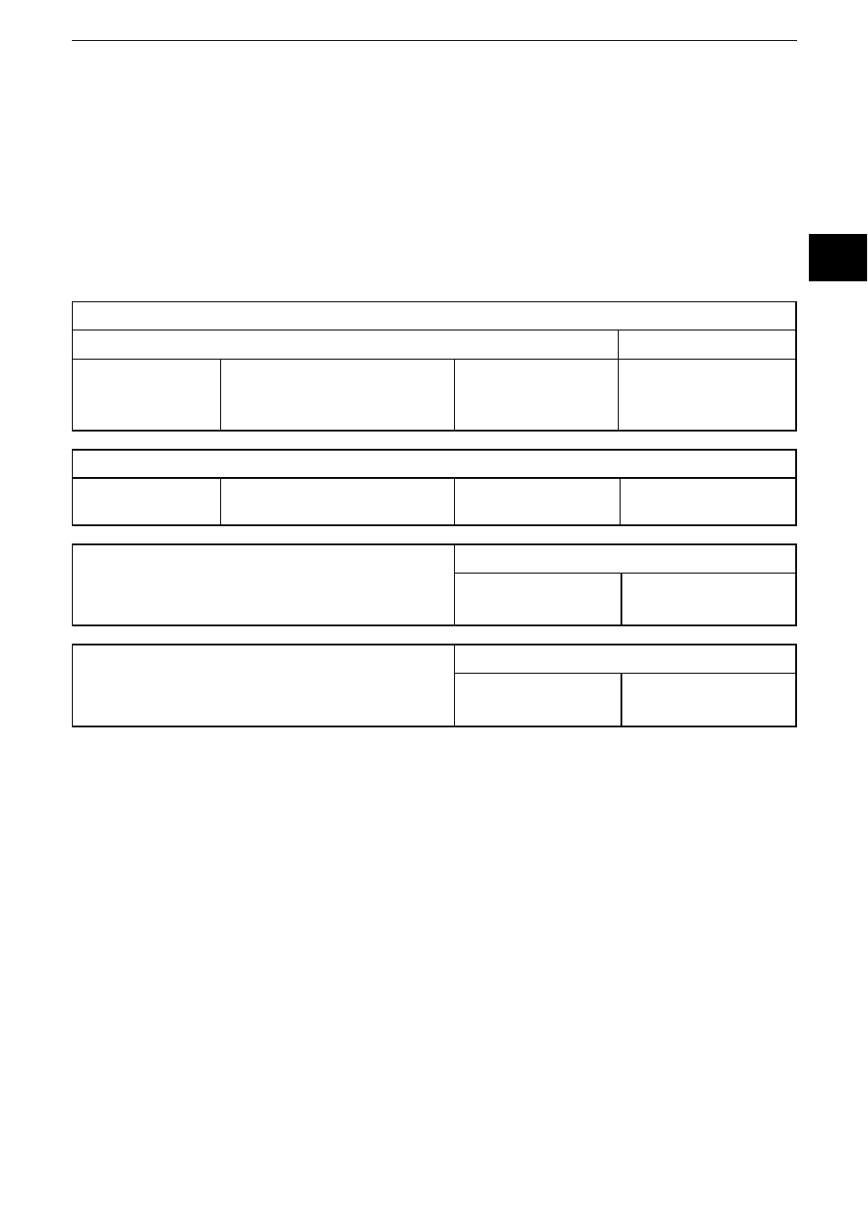
SAE J1939 uses 29-bit CAN identifier (extended frame format CAN 2�0B)� An SAE
J1939 message has the following structure:
SAE J1939 message
29-bit CAN identifier
Data
Priority
28…26
PGN
25���8
Source address
7���0
User data of the
message
0…8 bytes
Parameter Group Number (PGN)
Ext� data page 25
Data page 24
PDU format (PF)
23…16
Target address / group
extension (PS) 15…8
PDU format 1 (specific)
00h - EFh
23…16
Target address (DA)
15…8
PDU format 2 (global)
F0h - FFh
23…16
Group Extension (GE)
15…8
7.1.1 PDU format 1
This format defines a message which is sent to a defined unit� In this case the
PDU-specific byte (PS) is the target address (DA) of the unit� If the value of the
PDU format field (PF) is between 0x00 and 0xEF, it is a PDU format 1 message�
For proprietary (manufacturer-specific) messages the PDU format value 0xEF is
defined� Ext� data page bit = 0 and data page bit = 0�
7.1.2 PDU format 2
This format defines a message which is sent globally� In this case the PDU-
specific byte (PS) corresponds to the group extension (GE)� If the value of the
PDU format field (PF) is between 0xF0 and 0xFF, it is a PDU format 1 message�
For proprietary (manufacturer-specific) messages the area (PDU format PF) and
group extension (GE) 0xFF00 – 0xFFFF is defined�
Ext� data page bit = 0 and data page bit = 0