Henry Engineering DigiStor II User Manual
Page 2
4.0 OPERATION DigiStor II can be operated by either local or remote control.
4.1 LOCAL OPERATON: How to record and play messages using the pushbuttons on the unit.
4.1.1 RECORDING A MESSAGE (NOTE: The minimum message length is 2 seconds.)
1. Make necessary audio input and output connections to the system. Set OUTPUT LEVEL fully CW.
2. Push the RECORD SETUP button; Record LED will flash.* 3. Press the SELECT button to select the Message
# to be recorded. Message # LEDs will be ON if nothing has been recorded in that location, but will FLASH if there
is already a message recorded.
4. Feed audio into the DigiStor II while watching the AUDIO SENSE and OVERDRIVE LEDs. The AUDIO SENSE
LED should light to confirm audio is present. If the OVERDRIVE LED flashes, the input level it too high. Turn the
INPUT LEVEL control CCW until it goes out. (Audio signal will be heard through the OUTPUT jacks.)
5. Once audio levels have been set, begin recording by pressing the START/STOP button once. The RECORD
and MESSAGE # LEDs will remain ON during recording.
6. To stop recording, press the START/STOP button again. System will return to idle.
* Record Setup will time-out after 1 minute of inactivity.
4.1.2 PLAYING A MESSAGE: (NOTE: CONFIG switches do NOT affect play via pushbuttons on unit.)
1. Press the SELECT button to select Message # to play. SELECT button will only increment between valid
Message #s and the LEDs will flash.*
2. Press the START/STOP button to begin playback. Message # LED will stay ON during playback. 3. Press the
START/STOP button again to stop playback at any time.
* Playback message selection will time-out after 1 minute of inactivity.
4.2 REMOTE OPERATION: How to record and play messages via wired remote control.
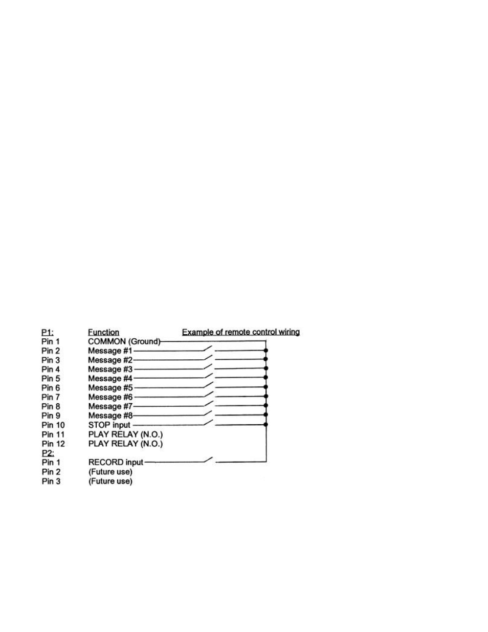
4.2.1 REMOTE CONTROL WIRING: DigiStor II remote control connectors must be wired as follows:
There are 2 connectors used for remote control of DigiStor II. Connector #1 (P1) and Connector #2 (P2). P1 is a
12-position pluggable connector used for remote control of Message Play, Stop, and for access to the PLAY
RELAY contacts. P2 is a 3-position connector used for remote control of the Record function. All Play, Stop, and
Record functions are triggered with contact closures to the "COMMON" (ground) pin, P1-1. Pin-outs are detailed
below:
4.2.2 "NORMAL MODE" RECORDING VIA REMOTE CONTROL (CONFIG Switch #3 UP): To record a
message, first activate the RECORD SETUP mode by providing a maintained contact closure between P2-1
(Record) and P1-1 (Common). The RECORD LED will flash. Next, provide a maintained contact closure between
the Message # to be recorded and Common. For example, to record Message #5, provide a maintained closure
between P1-6 and P1-1. Recording will begin; the RECORD and MESSAGE # LEDs will remain ON during
recording. Observe the AUDIO SENSE and OVERDRIVE LEDs to confirm correct audio levels. To stop recording,
release the Message # closure; release the remote Record input closure to exit the recording mode.
4.2.3
"PRIORITY MODE" RECORDING VIA REMOTE CONTROL (CONFIG Switch #3 DOWN): If Priority mode
is selected, DigiStor II will immediately begin recording Message #1 as soon as the remote Record circuit (P2-1) is