Spectrum Controls 140 MPM 204 00sc User Manual
Page 48
Quantum Series 140 MPM 204 00sc
50
Sample Configuration
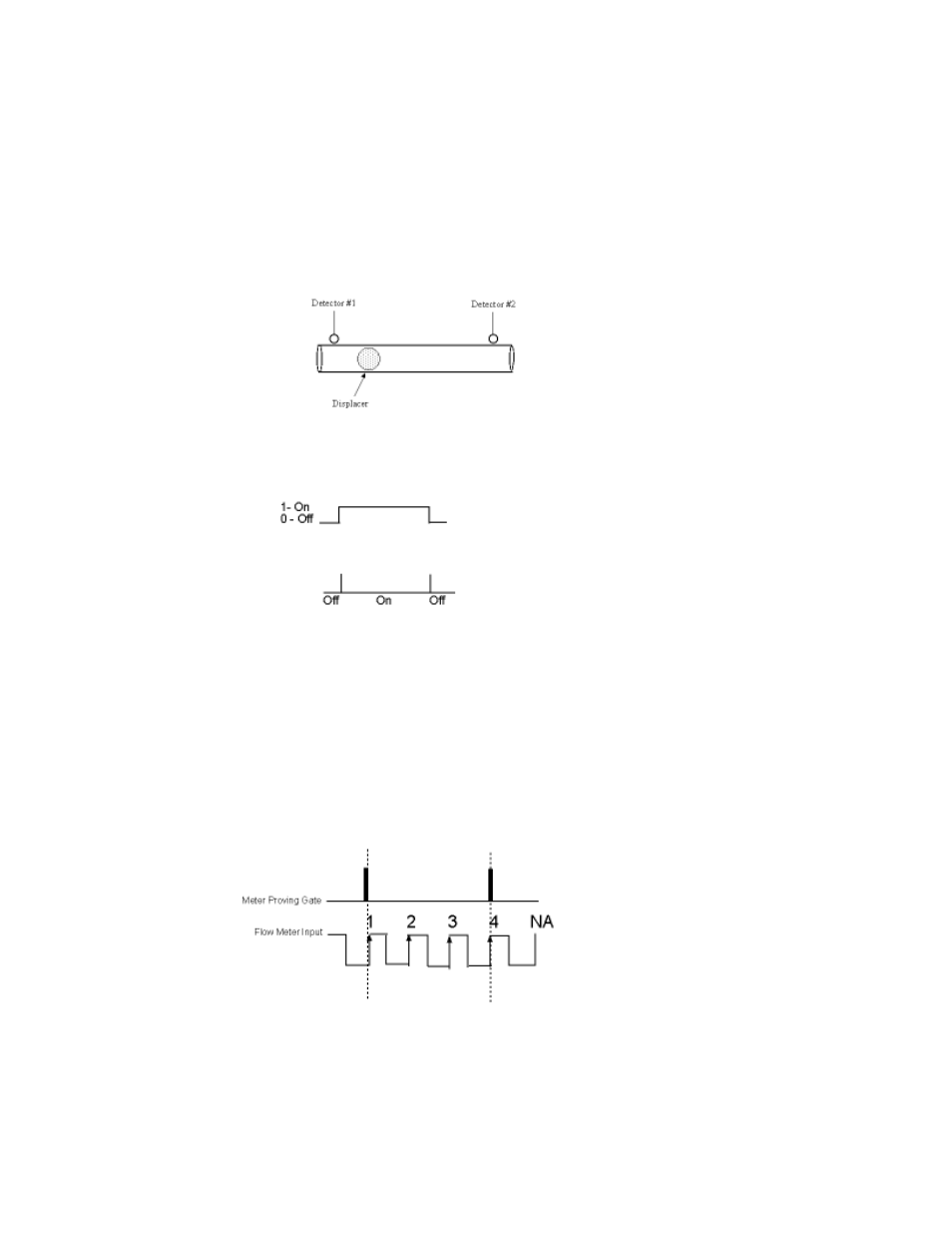
Using the Meter Proving Inputs
A ball proving system would use the meter proving input found on the module. The ball meaures the
flow velocity over a fixed length of line. When the ball crosses the starting point a momentary high
signal from a proximity switch starts the counter. When the ball crosses the prover exit another
proximity switch triggers causing the counter to stop. During the movement of the displacer the
meter count is monitored. Once complete the transit time is compared to the meter count. Any
difference in these values may be used to adjust the calibration (M factor) of the flowmeter.
The Meter Proving Inputs are designed for use with typical meter proving applications. These inputs
differ from the hardware inhibit/trigger inputs in the way the start and stop the counter.
Inhibit / Trigger Line
Meter Proving Input
The inhibit trigger line turns the counter on and off by holding the logic signal high or low. The
Meter Proving Input starts counter operation by applying a momentary high logic level signal
(pulse). The counter is stopped by applying another momentary high logic level signal (pulse).
Utilizing the meter proving input to start and stop count functions enables the user to count
pulses as fast as 20 microseconds to an accuracy of 1 count.
Here is an example wave form representing the start and stop transitions on the external gate
enable, and the associated pulses that the module would accumulate:
Given the above wave form, the module will begin counting the first positive going input pulse
after the external enable input goes low. The module will accumulate 4 counts in the channel count
register and stop when the external enable input goes high. The external enable line accommodates
5 Vdc, 12 Vdc and 24 Vdc signals and is pulled low internally.