Lingenfelter L460050000 Lingenfelter STOV-002 MPH Activated Switch v3.5 User Manual
Page 6
See the table below for the Function switch settings in each PPM range.
Wiring (also labeled on module):
Wire Color Label
Notes
Red
+12V Switched Power
Connects to a switched +12 volt source.
Black
Ground
Connects to a vehicle ground.
Yellow
Voltage Out
This is the vehicle speed output voltage (analog voltage
output). This is a 0-5 volt DC output.
Gray
Stage Out / Norm On
This is the first of two output wires. When used in MPH
activated switch mode, this wire connects to the ground
side of the device you plan to activate. When used in gear
mode, this wire activates the boost controller’s next stage.
Green
Activation Out / Norm Off This is the second output wire. When used in MPH
activated switch mode, this connects to the ground side of
the device you plan to activate. When used in gear mode,
this wire activates and deactivates boost control.
White
PPM Input Signal (VSS)
This is the vehicle speed pulse input. This connects to the
ECM/PCM Vehicle Speed Sensor (VSS) output signal.
Red LED:
• Solid red when powered up.
• Blinks whenever target MPH is reached.
Installation:
• Remove negative battery terminal.
• Connect black wire of MPH switch to a suitable
vehicle ground.
• Connect the red wire to a switched and fused
+12 volt DC source.
• Connect the white wire to the ECM or PCM
speed signal output wire (consult service
information or contact LPE for your specific
vehicle application).
• See Table C on page 10 for sample PCM/
ECM vehicle speed output pin/wire locations.
• If there is no wire in your vehicle speed output pin/wire location, you will need to enable the
VSS signal by re-calibrating the ECM, add a wire to the connector, and then add a pull-up resistor to
the circuit (See page 11 for pull-up resistor wiring instructions).
• Connect the output/control wires (green and gray) as needed for your application.
• See page 8 for example wiring schematics for MPH switch function.
• See page 9 for example wiring schematics for use with the LPE LNC-001R / LNC-002 /
LNC-003 / LNC-2000 launch controllers.
• Reconnect the negative battery terminal.
Page 5 of 12
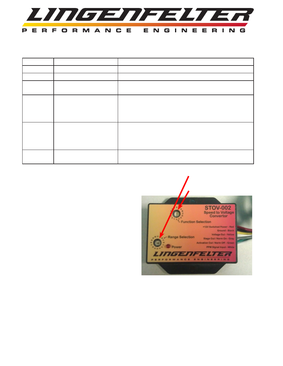
Function selection switch
Range Selection switch