General installation recommendations installation, Ferrites, Step 1 / 2 : preperation – Hatteland Display HM C01 (Rugged) User Manual
Page 17: Step 2 / 2: checklist, Fig1, Fig2
17
IND100210-9
General Installation Recommendations
Installation
Ferrites
The ferrites prevent high frequency electrical noise (radio frequency interference) from exiting or entering the
equipment. You can locate the loose ferrites (where applicable, check Contents of Package chapter in the user
manual) in the Accessories box which are part of the main computer unit packaging. Some products have also factory
mounted ferrites on internal connectors (where applicable).
The ferrites must be mounted on specificed cables to fully comply with the Type Approvals.
Step 1 / 2 : Preperation
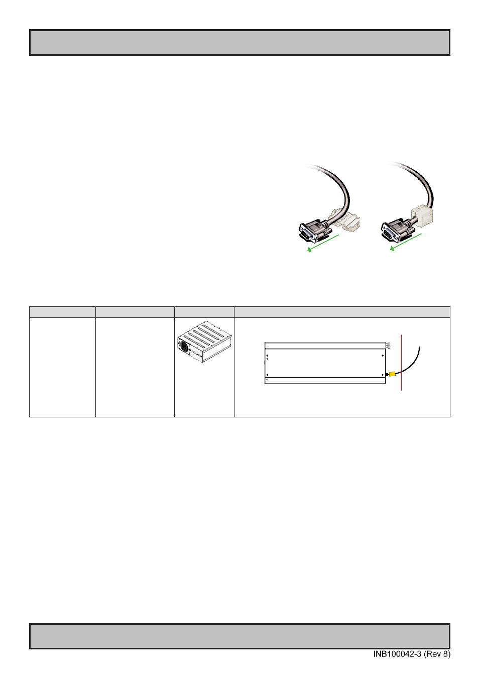
The ferrites should be mounted (clipped in place on the cable) and
located as close as possible to the connector piece that connects to
the rear of computer (maximum length from computer connector is
5cm [1.97 inch]). See checklist below.
When ready: Open the ferrite, place the cable inside as shown in
FIG1, and then gently close it until a click can be heard (FIG2). You
may close and re-open them as many times as required during the
installation.
Step 2 / 2: Checklist
Typenumber
Ferrites for Cables
Dimetric View
Perferred distance / location of ferrites. Computer shows side view
HM C01 STx-D601
HM C01 STx-D602
x=Operating System
16 x Würth 742 711 12:
For USB, Audio, COM,
Keyboard and Mouse
4 x Würth 742 711 31:
For Ethernet
1 x Würth 742 712 21:
For Parallel
Red Line indicate 5cm [1.97 inch] limit from connector (black square).
Do not mount ferrites (orange square) located beyond the red line!
Note: If you have many cables, mounting ferrites might have to be
arranged as a alternating stair-step like pattern. This is to prevent clumps
of ferrites that might apply tension to the connected connectors.
FIG1
To computer
FIG2
To computer