VACUUBRAND PC 2001TE VARIO User Manual
Page 13
page 13 of 50
Documents are only to be used and distributed completely and unchanged. It is strictly the users´ responsibility to check
carefully the validity of this document with respect to his product. manual-no.: 99 91 35 / 11/04/2008
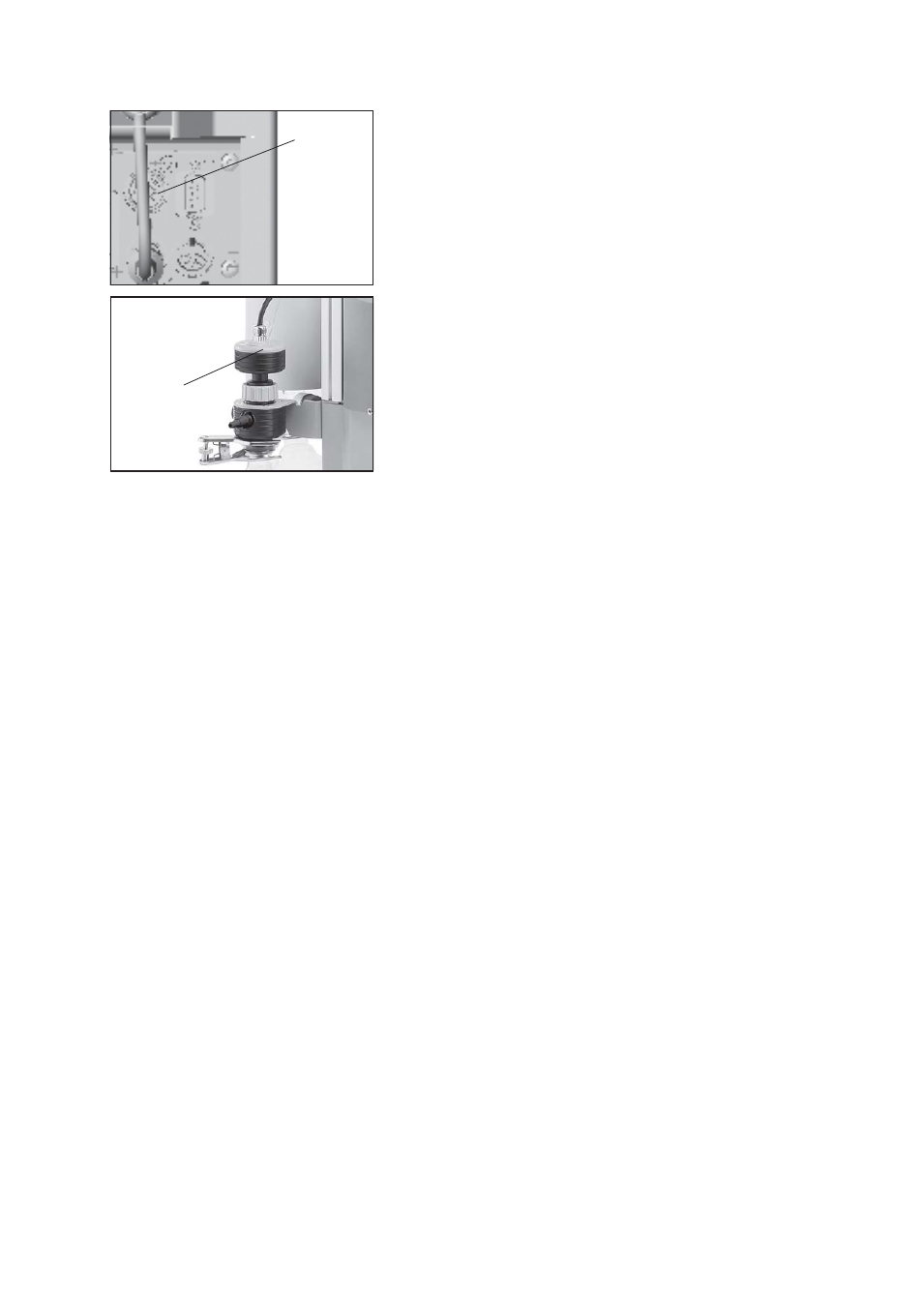
pressure
transducer
VSK 5
connector
for VSK 5
The cable of the gauge head is connected to the female con-
nector at the rear side of the vacuum controller.
The gauge head is connected to the vacuum system with a
union nut using an adapter.
☞ The device is adjusted together with the gauge head at the
factory. If the gauge head is replaced a readjustment is rec-
ommended.
Max. permitted pressure at the pressure transducer: 1.5 bar (ab-
solute).
☞ The display flashes at a pressure higher than 1100 mbar.
☞ Obey max. permitted pressure.
☞ Inside a vacuum system where evaporation occurs, e. g.
rotary evaporator, the vacuum is not uniform, e. g. a con-
denser acts as pump or the vacuum in the pipeline is lower
than in the system. Therefore carefully choose position where
to connect the gauge head.
☞ Condensate and deposits in the pressure transducer affect the measuring result.
☞ In case of deposits, aggressive or condensable media, install a gas washing bottle before the pressure
transducer if necessary.
☞ In order to avoid malfunction it is important to position the pressure transducer in the vacuum line so as
to avoid flow of condensate towards the pressure transducer.
☞ Clean pressure transducer if necessary, see section “maintenance“.
☞ Setting of interface parameters, see section “Interface“.
☞ Preselections at the controller, see section “Modes“.
☞ Use and operation of the controller see section “How to operate the controller”.
Notes regarding the assembling of the pressure transducer VSK 5
The pressure transducer can be disassembled from the inlet of the pumping unit and, after having unscrewed
the adapter, assembled using a small flange connection or a hose nozzle (included in delivery) directly to
the apparatus.
Close the connection at the inlet of the pumping unit using a blind cap (cat. no.: 67 71 50).