Control elements – MUTEC MC-3.2 Smart Clock HD User Manual
Page 9
> > > > > > > > > > > > > > > > > > > > > > > > > > > > > > > > > > > > > > > > > > > > > > > > > > > > > > > > > > > > > > > > > > > >
88
\
B E D I E N E L E M E N T E
B E D I E N E L E M E N T E
B E D I E N E L E M E N T E
> > > > > > > > > > > > > > > > > > > > > > > > > > > > > > > > > > > > > > > > > > > > > > > > > > > > > > > > > > > > > > > > > > > >
Manual SDs-01 D 3.2.2003 17:45 Uhr Seite 3
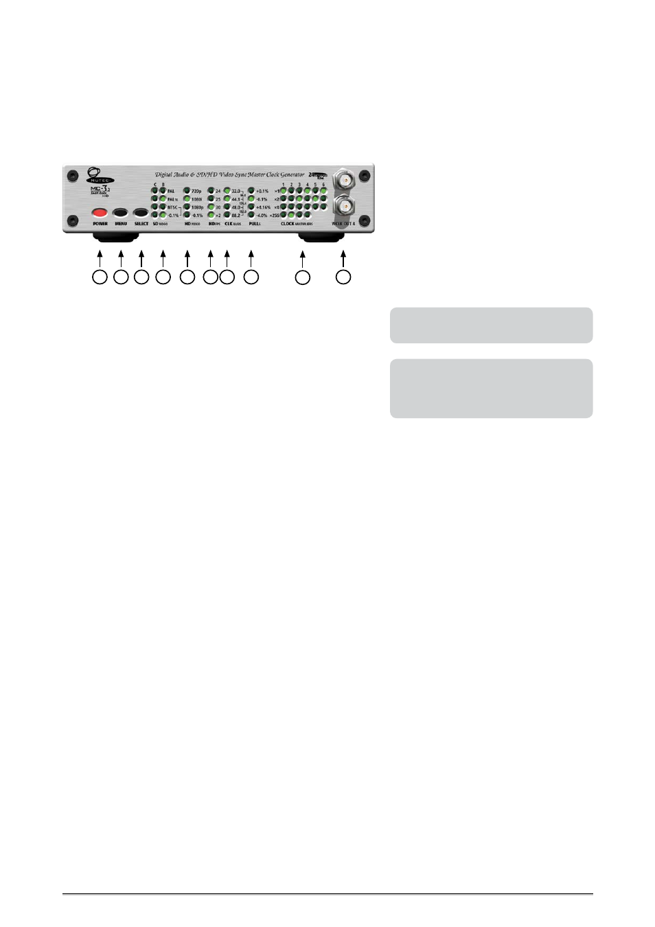
CONTROL ELEMENTS
MC-3.2 SMART CLOCK HD Front Panel
1 POWER
This red LED lights up when the unit is switched on with the rear panel
POWER switch (on condition that the adjusted voltage matches your local
voltage).
2 MENU
Use this key to access the different functional menus.
3 SELECT
Use this key to select a function from a specific functional menu.
4 SD
VIDEO
This functional menu lets you choose between different SD video standards,
output formats and frame rates.
5 HD
VIDEO
+ HD
FPS
These two functional menus are working simultaneously together and let
you choose between different HD tri-level video standards (HD
VIDEO
)
in
combination with different and frame rates (HD
FPS
).
6 CLK
BASIS
This functional menu enables the setting of the basis audio clock rate
between 32.0kHz and 192.0kHz which applies to all Word Clock, AES/EBU
and S/PDIF outputs.
7 PULL
S
This functional menu allows for adding the common pull up and pull down
frequency factors to the basis audio clock rate setting for film/video and
audio transfers.
8 CLK
MULTIPLIERS
This functional menu lets you determine the factor by which the basis audio
clock rate is multiplied additionally. This setting can be made individually
for every Word Clock pair of outputs as well as for the AES/EBU and S/PDIF
outputs.
9 WCLK OUT 4
This pair of Word Clock outputs transfers either all standard Word Clock
rates as well as Word Clock x 256 for older digidesign ProTools™ systems.
Their numbering is aligned to the corresponding functional menu on the
front panel. For adjusting these outputs see chapter OPERATION.
For detailed specifications on all terminals,
refer to the »Pin Assignment of the
Connectors« and »Technical Data« in the
chapter APPENDIX.
Refer to the OPERATIONS chapter for more
information.
9
9
4
3
2
5
1
5
6
7
8