Intek 200 User Manual
Page 23
-21-
I : \ O F F I C E \ W P M A N U A L \ M a n 2 0 0 r v b . w p d
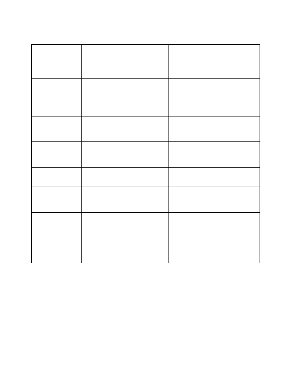
TABLE III. Trouble Shooting Guide - Instrument diagnosed problems
OBSERVATION
PROBABLE CAUSE
ACTION
'GENERAL FAULT'
'MODE 0'
1. Cable cut or not connected at all
1. Check cable for contact and
continuity
'GENERAL FAULT'
'MODE 1'
1. Improper cable hookup
2. Failed A/D circuit. Short between
sensor terminals O and BLU of
JP2.
3. Damaged flow sensor
1. Verify cable hookup is correct
2. Check cable connections for proper
contacts or moisture & corrosion
3. * Contact factory
'GENERAL FAULT'
'MODE 2'
1. Cable contact corroded
2. Damaged flow sensor
1. Check both ends of cable for
moisture or corrosion
2. * Contact factory
'GENERAL FAULT'
'MODE 3'
1. Shorted cable connection
2. Damaged flow sensor
1. Check for short in cable due to
moisture or corrosion
2. * Contact factory
'GENERAL FAULT'
'MODE 4'
1. Blown heater fuse at F1
2. Damaged flow sensor
1. Check wiring and replace fuse
2. * Contact factory
'GENERAL FAULT'
'MODE 5'
1. Sensor’s heater connection is open
between terminal O and R of JP2
2. Damaged flow sensor
1. Check sensor heater for an open
connection
2. * Contact factory
'GENERAL FAULT'
'MODE 6'
1. Temperature is above the specified
maximum (see instrument tag)
2. Possible sensor damage
1. Record temperature and remove
sensor from flow stream
2. * Contact factory
Oscillating status
output and/or
flashing display.
1. Software malfunction or corrupt
calibration parameters.
2. Failed electronic component.
1. Contact factory regarding restoring
factory calibration parameters.
2. * Contact factory
* Complete Table IV before contacting factory.