Bryant Air Coold Split System 575B User Manual
Page 15
—
15
—
PRE-START-UP
IMPORTANT: Before beginning Pre-Start-Up or Start-Up,
review Start-Up Checklist at the back of this book. The
checklist assures proper start-up of the system and provides
a record of unit condition, application requirements, system
information, and operation at initial start-up.
I. PRELIMINARY CHECKS
1. Check all air handler and other equipment auxiliary
components. Consult manufacturer’s instructions
regarding any other equipment attached to unit. If
unit has field-installed accessories, be sure all are
properly installed and correctly wired. If used, air-
flow switch must be properly installed. See Fig. 14 for
typical field wiring.
2. Backseat (open) compressor suction and discharge
valves. Now close valves one turn to allow refrigerant
pressure to reach test gages.
3. Open liquid line service valve.
4. Check tightness of all electrical connections.
5. 541A180 only — compressor oil level should be visible
in sight glass. Adjust the oil level as required. No oil
should be removed unless the crankcase heater has
been energized for at least 24 hours. See Start-Up
section, Preliminary Oil Charge.
NOTE: 575B, 575C units do not have a compressor oil
level sight glass. These units are factory charged with
the required amount of oil. If required, use the follow-
ing oil for replacement: For 575B and 541A units use
Zerol 150, part number P903-2001. For 575C units
use R015, part number P903-0101.
6. Leak test the entire refrigerant system using soap
bubbles and/or an electronic leak detector. Evacuate
and dehydrate entire refrigerant system.
7. Electrical power source must agree with nameplate
rating.
8. Turn on crankcase heater for 24 hours before starting
the unit to be sure all refrigerant is out of the oil. To
energize crankcase heater, perform the following
steps:
a. Set the space thermostat system switch to OFF, or
adjust the temperature so there is no demand for
cooling.
b. Close the field disconnect.
c. Leave the compressor circuit breaker off. The
crankcase heater is now energized.
9. As shipped, compressor is held down by 4 bolts. After
unit is installed, loosen each bolt and locknut until
flat washer or snubber can be moved with finger pres-
sure. Be sure compressor floats freely on the mount-
ing springs (541A units only). See Fig. 15A and 15B
for compressor mounting.
II. PRELIMINARY
CHARGE
Before starting the unit, charge liquid refrigerant into the
high side of the system through the liquid service valve. The
amount of refrigerant added must be at least 80% of the
operating charge listed in the Physical Data table (Table 1,
page 6). Allow high and low side pressures to equalize before
starting compressor. If pressures do not equalize readily,
charge vapor on low side of system to assure charge in the
evaporator. Refer to GTAC II, Module 5, Charging, Recovery,
Recycling, and Reclamation for liquid charging procedures.
III. LIQUID LINE SOLENOID
To minimize refrigerant migration to the compressor during
the heat pump OFF cycle, the 575B,C unit must have a
bi-flow liquid line solenoid valve (field supplied). The valve
opens when the compressor is energized, and closes when
the compressor is deenergized. This reduces compressor
flooded starts, thus significantly increasing compressor life.
IV. ACCUMULATOR
The unit accumulator controls the rate of liquid refrigerant
to the compressor during heat pump operation.
The 541A accumulator features a unique method for
returning oil to the compressor. The oil return mechanism is
external to the accumulator. The mixture of oil and refriger-
ant is metered to the compressor by a brass orifice which is
removable and cleanable. The oil return mechanism also
contains a solenoid valve that opens when the compressor is
ON and closes when the compressor is OFF. This keeps the
liquid refrigerant stored in the accumulator from draining to
the compressor during the heat pump OFF cycle, which
further protects the compressor against flooded starts.
CAUTION: Do not attempt to start the heat pump
system, even momentarily, until the following steps
have been completed. Compressor damage may result.
CAUTION:
Prior to starting compressor, a preliminary
charge of refrigerant must be added to avoid possible
compressor damage.
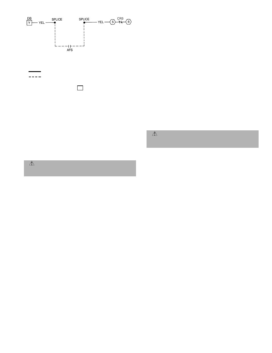
LEGEND
NOTES:
1. Locate YEL wire between
on DB and terminal 5 of CR3
and cut.
2. Splice airflow switch (AFS) (field supplied) contact wires (field
provided) to two ends of cut YEL wire as depicted.
Fig. 14 — Typical Field Wiring for Airflow Switch —
541A180/524A-H
AFS — Airflow Switch (Sail Switch)
CR
— Control Relay
DB
— Defrost Board
Factory Wiring
Field Control Wiring
Y