Pply the, Ads to a – Wood’s Powr-Grip PT10FS10TAC User Manual
Page 11
Rev 9.0/1-12
9
PT10HV11FAC: #35142
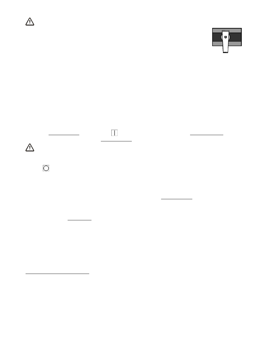
WARNING: Closing any pad shutoff reduces lifting capacity.
To activate a pad, open the pad shutoff (place valve lever
parallel
with
vacuum line); to deactivate a pad, close the pad shutoff (place valve lever
perpendicular
to vacuum line). To calculate the lifting capacity when some
pads are deactivated, consult the Per-Pad Load Capacity rating (see
SPECIFICATIONS) and multiply by the number of pads currently
activated.
Note that calculated capacities may not exceed the
Maximum Load Capacity
(see SPECIFICATIONS in main instructions).
Always activate pads in a symmetrical configuration, to keep the lifter
balanced while lifting, and use as many pads as possible for each load being lifted, to maximize
lifting capacity and to minimize load overhang.
T
O
A
PPLY THE
P
ADS TO A
L
OAD
Generating Vacuum Flow
Place the power switch in the ON (
) position. This engages the vacuum pump, causing air
to be drawn immediately at the vacuum pads.
6
WARNING: Never turn power off during operation; keep pump running
throughout lift.
The lifter is designed for the vacuum pump to run continuously. Placing the power switch in the
OFF (
) position during lifter operation could result in the release of the load and possible
injury to the operator (see T
O
L
IFT AND
M
OVE THE
L
OAD
: In Case of Power Failure to follow).
Positioning the Lifter on the Load
Make certain that the contact surfaces of the load and all vacuum pads are free of any
contaminates that could prevent the pads from sealing against the load (see MAINTENANCE:
V
ACUUM
P
AD
M
AINTENANCE
).
Center the lifter’s pad frame to within 2" [5 cm] of the load center, since off-center loading can
interfere with the lifter’s tilt capability (see T
O
T
ILT THE
L
OAD
to follow), and it may also damage
the lifter.
7
Make sure that all activated pads will fit entirely on the load’s contact surface (see
SPECIFICATIONS: Pad Spread) and that they will be loaded evenly while lifting (see
SPECIFICATIONS: Per-Pad Load Capacity). Then apply the lifter to the load until all pads seal
against the contact surface.
6
If the vacuum pump or any other powered component fails to function while the power switch is in the ON position, make sure
the lifter is connected correctly to an appropriate power source, as directed in the ASSEMBLY section. If so, examine each circuit
breaker (adjacent to power switch) to determine whether it has interrupted the electrical circuit to the component. Although the
operator can reset the circuit breaker, the power interruption may indicate an electrical problem that requires attention. Correct
any deficiency before resuming normal operation of the lifter (see wiring diagram provided).
7
The lifter is designed to handle the maximum load weight (see SPECIFICATIONS: Maximum Load Capacity) when the load’s
center of gravity is positioned within 2" [5 cm] of the pad frame’s center point. Occasional loading deviations are permissible,
provided that the operator can maintain control of the load at all times and that the load weight is low enough to avoid damaging
the lifter.
CLOSED
PAD SHUTOFF VALVE