Hutoffs, Pply the, Ads to a – Wood’s Powr-Grip MT10FS10TAIR User Manual
Page 12: Positioning the lifter on the load
Rev 25.0/5-14
10
MT-FS10TAIR: #35090
T
O
U
SE
P
AD
S
HUTOFFS
Each shutoff on the pad frame controls the vacuum line to the adjacent vacuum pad. By
activating or deactivating the vacuum flow at specific pads, the operator can use the lifter to
handle loads of various weights and dimensions (see Load Capacity and Pad Spread in
SPECIFICATIONS). In addition, certain pads may be deactivated in order to avoid holes in the
load surface. To support the maximum load weight and larger load dimensions, all pads must be
activated; for smaller weights and dimensions, some pads may be deactivated,
provided that
the lifter still has sufficient capacity to support the load
(see INTENDED USE: L
OAD
C
HARACTERISTICS
).
WARNING: Closing any pad shutoff reduces lifting capacity.
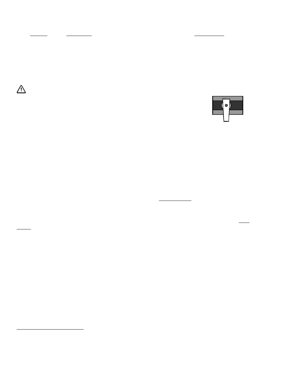
To activate a pad, open the pad shutoff (place valve lever
parallel
with
vacuum line); to deactivate a pad, close the pad shutoff (place valve lever
perpendicular
to vacuum line). To calculate the lifting capacity when some
pads are deactivated, consult the Per-Pad Load Capacity rating (see
SPECIFICATIONS) and multiply by the number of pads currently
activated. Always activate pads in a symmetrical configuration, to keep
the lifter balanced while lifting, and use as many pads as possible for
each load being lifted, to maximize lifting capacity and to minimize load
overhang.
T
O
A
PPLY THE
P
ADS TO A
L
OAD
Positioning the Lifter on the Load
Make certain that the contact surfaces of the load and all vacuum pads are free of any
contaminates that could prevent the pads from sealing against the load (see MAINTENANCE:
V
ACUUM
P
AD
M
AINTENANCE
).
The lifter is designed to automatically carry the load in an upright orientation. Center the pad
frame from left to right on the load. Determine which will be the top edge of the load while
lifting, and position the long row of vacuum pads near that edge.
5
This position will maximize
stability while lifting the load. Make sure that all activated pads will fit entirely on the load’s
contact surface (see SPECIFICATIONS: Pad Spread) and that they will be loaded evenly while
lifting (see SPECIFICATIONS: Per-Pad Load Capacity).
5
This is the
only row of pads on models MT4FS10TAIR and MT6FS10TAIR.
CLOSED
PAD SHUTOFF VALVE