Ift and, Ove the, About the tilt linkage – Wood’s Powr-Grip MRTA611LDC User Manual
Page 17: Engaging or disengaging tilt locks, Load capacity and the warning light
Rev 14.0/5-13
15
MRTA6-DC: #35072
T
O
L
IFT AND
M
OVE THE
L
OAD
About the Tilt Linkage
WARNING: Make sure load is positioned correctly on lifter; unbalanced loads
may tilt unexpectedly.
The lifter’s tilt linkage is designed to automatically hold a balanced load in either the upright or
the flat position. However, an unbalanced load may tilt unexpectedly from the flat position to the
upright position, or vice versa, when lifted. This could result in load damage or injury to anyone
positioned in the tilt path of the load. To minimize the potential for these problems, make certain
prior to lifting any load
that it has allowable characteristics (see INTENDED USE: L
OAD
C
HARACTERISTICS
) and is attached correctly to the lifter (see T
O
A
PPLY THE
P
ADS TO A
L
OAD
preceding).
Engaging or Disengaging Tilt Locks
The tilt locks can be used to prevent unexpected tilting motion. Since the lifter is designed to
maintain either the vertical or the horizontal pad frame orientation when correctly loaded, the tilt
locks should only be needed if the operator is not able to maintain control of the load using the
control handle or other appropriate means. For example, if the lifter is being used to install glass
in a multi-story building, engaging the tilt locks would prevent the load from accidentally tilting
due to wind loads or other causes of incidental loading. Tilt locks are intended as a secondary
safety device and do not eliminate the need to center the load correctly on the pad frame (see
T
O
A
PPLY THE
P
ADS TO A
L
OAD
: Positioning the Lifter on the Load preceding).
CAUTION: Failure to center load correctly may
damage tilt locks or other lifter
components.
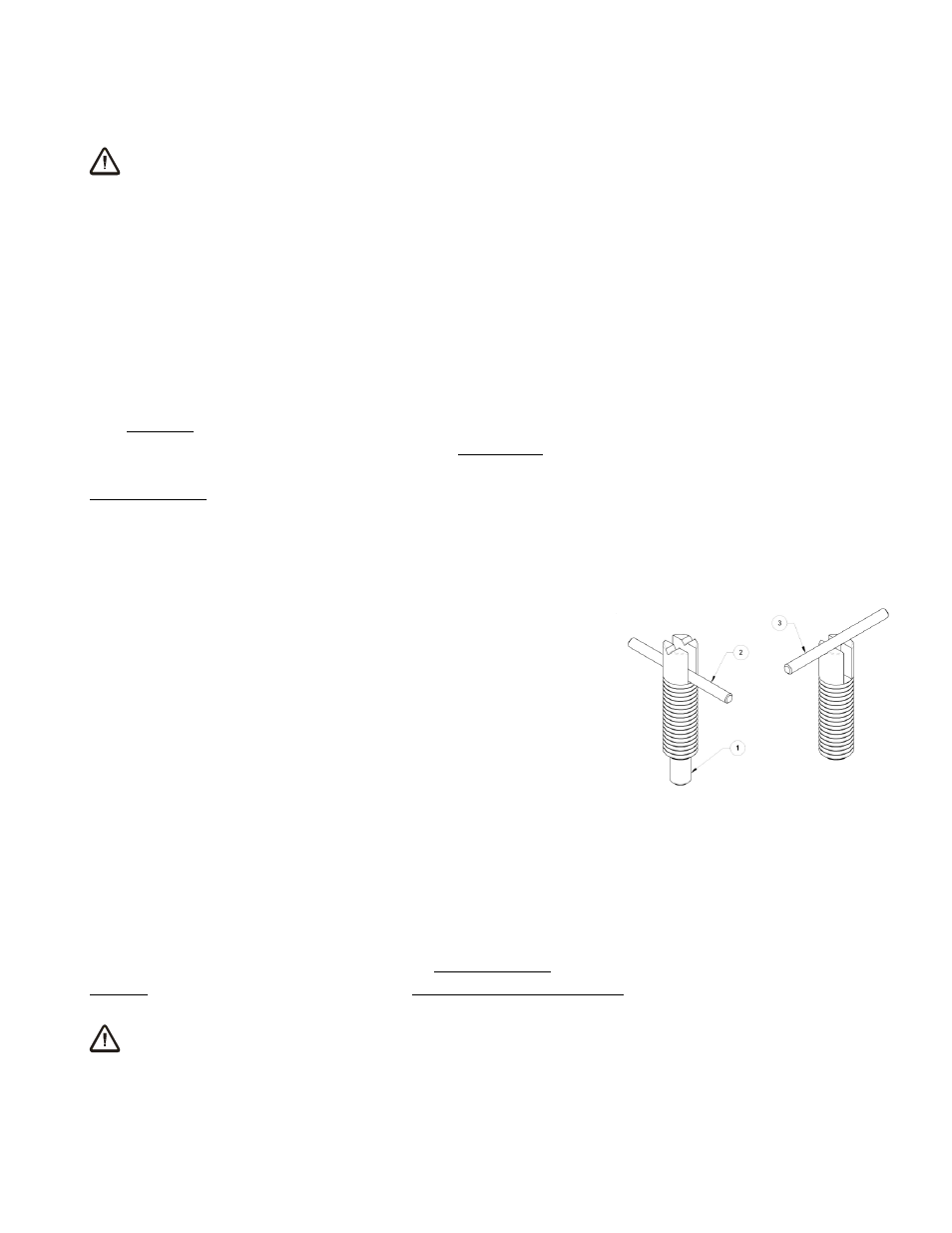
To engage the tilt locks, first make sure the pad frame is
oriented in either the horizontal or the vertical position. Then
turn the T-handles on the spring plungers to the engaged
position, making sure that the noses of both spring plungers
are fully inserted in the notches on the plates where the lifter's
tilt linkage attaches. To disengage the tilt locks, pull the T-
handles outward and turn them to the disengaged position,
making sure that the noses of both spring plungers are fully
retracted from the notches before attempting to tilt the pad frame.
Load Capacity and the Warning Light
The lifter's Load Capacity is rated at a vacuum level of 16" Hg [-54 kPa] (see SPECIFICATIONS).
After the lifter has attained this level, the vacuum pump turns off automatically, to conserve
battery energy. At the same time, the low vacuum warning light turns off, to indicate that the
lifter is ready to lift the maximum load weight.
WARNING: Never attempt to lift load while red warning light is illuminated.
Do not attempt to lift the load while the warning light is illuminated; such an attempt could result
in a load release and possible injury to the operator.
SPRING PLUNGERS
1 NOSE
2 T-HANDLE - ENGAGED
3 T-HANDLE - DISENGAGED