Confirming the pad frame configuration, Pply the, Ads to a – Wood’s Powr-Grip MRTA611LDC User Manual
Page 15: Positioning the lifter on the load, Sealing the pads against the load
Rev 14.0/5-13
13
MRTA6-DC: #35072
CAUTION: Examine each air filter regularly, and empty when necessary.
Two air filters help protect the vacuum generating system from contaminants. However, the
lifter is not intended for use on wet load surfaces because the filters would not prevent liquid
from entering the vacuum system. The operator must examine each filter bowl regularly and
remove any liquid or other contaminants found inside (see MAINTENANCE: A
IR
F
ILTER
M
AINTENANCE
).
Confirming the Pad Frame Configuration
WARNING: Load capacity of lifter can vary, depending on pad frame
configuration.
Make sure the pad frame has been assembled in the configuration that will provide optimal
support of the load while lifting (see ASSEMBLY: T
O
C
HANGE THE
P
AD
F
RAME
C
ONFIGURATION
). The
pad frame configuration selected must be appropriate, both for the weight and for the
dimensions of the load in question.
T
O
A
PPLY THE
P
ADS TO A
L
OAD
Positioning the Lifter on the Load
Make certain that the contact surfaces of the load and all vacuum pads are free of any
contaminates that could prevent the pads from sealing against the load (see MAINTENANCE:
V
ACUUM
P
AD
M
AINTENANCE
). Center the lifter’s pad frame to within 2" [5 cm] of the load center,
since off-center loading can cause the load to tilt or rotate unexpectedly (see T
O
L
IFT AND
M
OVE
THE
L
OAD
: About the Tilt Linkage and T
O
R
OTATE THE
L
OAD
E
DGEWISE
to follow), and it may also
damage the lifter.
8
Make sure that all vacuum pads will fit entirely on the load’s contact surface
(see SPECIFICATIONS: Pad Spread) and that they will be loaded evenly while lifting (see
SPECIFICATIONS: Per-Pad Load Capacity). Then apply the lifter to the load so that all pads are
touching the contact surface.
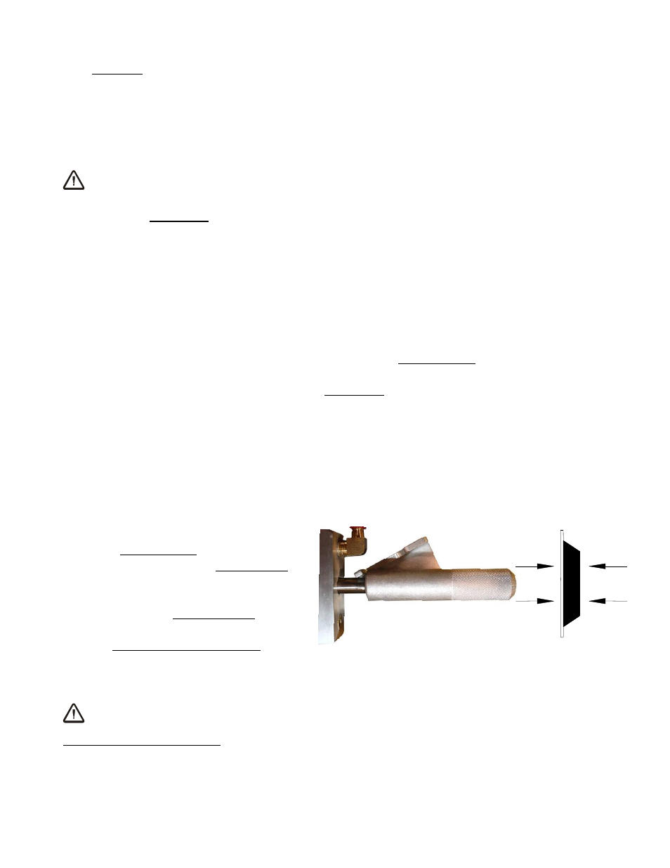
Sealing the Pads against the Load
Firm pressure at the center of the lifter
helps the vacuum pads begin to seal
against the load. Pull the valve handle
outward until it latches securely in the
“APPLY” position (power on), as shown.
This energizes the vacuum pump, causing
air to be drawn at the pads immediately.
The red low vacuum warning light also
turns on and remains illuminated until the lifter attains sufficient vacuum to lift the maximum
load weight (see T
O
L
IFT AND
M
OVE THE
L
OAD
: Load Capacity and the Warning Light to follow). The
valve handle must remain in the “APPLY” position throughout the entire lift.
WARNING: Keep valve handle latched securely in “APPLY” position throughout
lift.
8
The lifter is designed to handle the maximum load weight (see SPECIFICATIONS: Maximum Load Capacity) when the load’s
center of gravity is positioned within 2" [5 cm] of the pad frame’s center point. Occasional loading deviations are permissible,
provided that the operator can maintain control of the load at all times and that the load weight is low enough to avoid damaging
the lifter.
TO APPLY