Components, Orangutan sv-xx8 power & motor connections – Pololu Orangutan LV-xx8 User Manual
Page 7
4. Module Pinouts, Component Identification, and Usage Notes
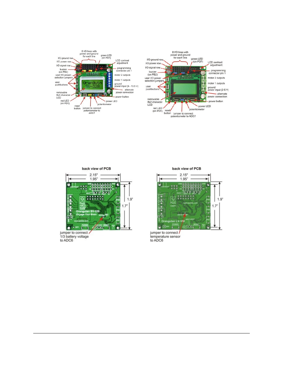
Components
Orangutan SV-328 top view with
components labeled.
Orangutan LV-168 features (top view).
The Orangutan contains a programmable ATmega168 or ATmega328P AVR microcontroller, a dual motor driver for
direct control of two DC motors, an 8×2 character LCD, a buzzer, three user pushbuttons, two user LEDs, and a
10k user trimmer potentiometer. These and the rest of the main features of the Orangutan modules are labeled in the
pictures above. Most of the connections points are also indicated on the silkscreen on the back side of the PCB, as
shown below. The overall unit dimensions are 2.15" x 1.9", and four 0.086" mounting holes, suitable for #2 screws,
are located 0.1" from the corners of the board (the top-left mounting hole is usually obscured by the buzzer).
Orangutan SV-328 bottom view.
Orangutan LV-168 PCB bottom view.
Orangutan SV-xx8 Power & Motor Connections
The power and motor connections are on the right side of the unit. The Orangutan SV-xx8’s input voltage should
be 6 – 13.5 V, from which the on-board regulator generates the 5 V that is used to power the logic. In its factory
configuration, analog input ADC6 is connected through a jumper to a third of the battery voltage so that you can
monitor the state of your batteries.
The Orangutan SV-xx8’s TB6612FNG motor driver can deliver a continuous 1 A per motor channel, and can briefly
deliver up to 3 A per motor channel. If you aren’t taking extra steps to keep the motor driver cool, such as using a
heat sink, exceeding this continuous current rating for too long will cause the motor driver to heat up and trigger its
built-in thermal shutdown.
Pololu Orangutan SV-xx8 and LV-xx8 User's Guide
© 2001–2014 Pololu Corporation
4. Module Pinouts, Component Identification, and Usage Notes
Page 7 of 18