INCRA Miter Slider User Manual
Page 3
INCRA MITER SLIDER OWNER’S MANUAL & JIG PLANS
©2007 by Taylor Design Group. All rights reserved. Rev.08.17.07
Page 3
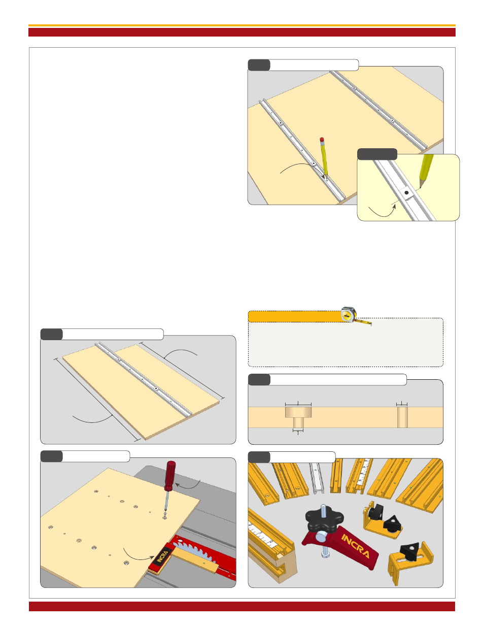
4. Carefully slide your jig platform out of the miter slots.
The Miter Sliders should be firmly attached. Remove the
dimes from your miter slots. Flip the base panel over and
mark the drill center locations for mounting holes through
the threaded holes in the Miter Sliders,
Fig. 5. Place a mark
on each side of the bar at the expansion screw locations to
aid in later locating and drilling access holes,
Detail 5A.
After marking your panel, pull the Miters Sliders off and
remove the double-sided tape.
5. Mounting hardware includes 3 ea #10-24 x 1/2” Phillips
machine screws and washers. These will be used to secure
the Miter Slider to your jig base. (The additional 3/4” screws
are for mounting to Build-It Panels as described on page 4.)
On jig bases less than 15” long, only two mounting screws
need to be used. Jig bases longer than 15” should use a
mounting screw in the first hole, the last hole, and one of the
interior holes,
Fig. 6.
6. Drill a 1/4” hole at each of the selected locations.
Counterbore each mounting hole from the top of the panel
with a 5/8” Forstner bit. The depth of the counterbore is
1/4”. Note: If you are using a 3/4” panel, make the counter-
bore 1/2” deep, or use longer mounting screws. It is not
necessary to counterbore the expansion screw access
locations,
Fig. 7.
7. Mount the Miter Sliders to your jig platform using the
included hardware. Before tightening the fasteners, slide
the Miter Sliders back into your miter slot and square the
edge of the base panel with the saw blade,
Fig. 8. Securely
tighten the fasteners.
Fig. 5
Mark Mounting Holes
Fig. 7
Hole Dimensions (1/2” sheet stock)
Fig. 6
Mounting Hole Locations
Fig. 9
Jig Accessories
Fig. 8
Square Jig Base
Detail 5A
Tip: Adjusting your jig
The drill and counterbore dimensions are slightly oversized to allow
some adjustment of the jig’s angle later on. By loosening the mounting
fasteners and twisting the jig platform, you can change the angle by ± 2°.
Be sure to always re-tighten the mounting screws before using your jig.
Tip: Adjusting your jig
Mark drill center
location for Miter Sliders
Mark
expansion
mechanism
locations
Less than 15” use
mounting holes
a and C
Greater than 15”
use mounting holes
A, C and D
5
/
8
” dia x
1
/
4
” deep
counter bore
1
/
4
” dia expansion
screw location
1
/
4
” dia through hole
Second:
Tighten all mounting
screws
First:
Square jig base to blade
a
B
C
D
Now you can continue by adding all the things that make your
jig unique for the cutting situations in your shop, from bridges
and fences to T-Tracks, hold downs and toggle clamps, Fig. 9.
See pages 4-8 for some great jig and fixture ideas featuring
the new Incra Build-It System modular jig and fixture compo-
nents. Also, keep an eye on our website at www.incra.com
for free plans for the jigs shown in this manual as well as
others as they become available.