Installation instruc tio ns – Poison Spyder JK 07-10 BOLT-TOGETHER TRAIL CAGE User Manual
Page 7
INSTALLATION INSTRUC
TIO
NS
©2010 POISON SPYDER CUSTOMS, INC. • 951-849-5911 • WWW.POISONSPYDER.COM
Poison Spyder Customs • JK BOLT-TOGETHER TRAIL CAGE KIT
Page 7
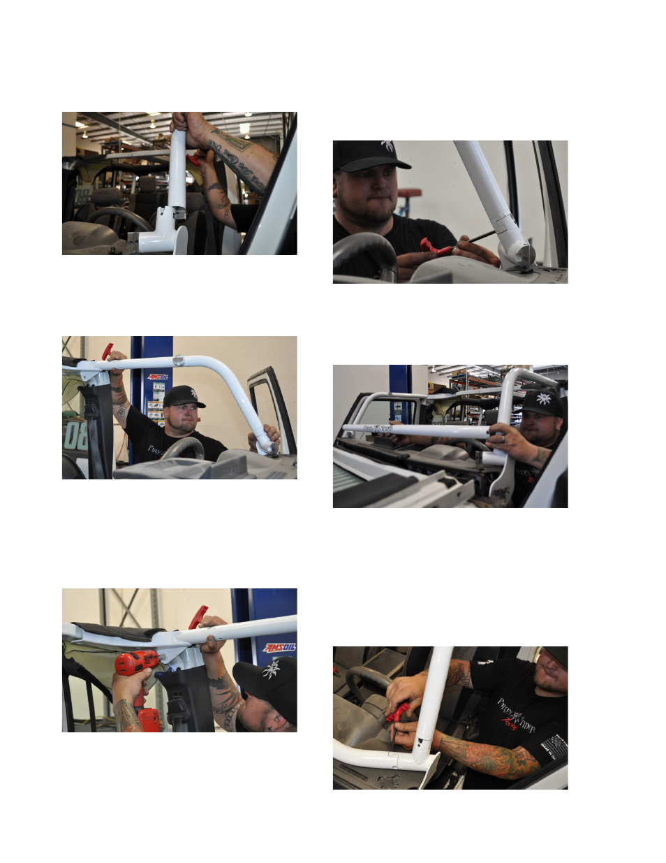
the connection where the interlocking tube
couplers meet at the top of the A-Pillar
Assembly.
FIGURE 23
28. While holding the Header Bar to A-Pillar joint
together, fit the upper end of the Header Bar
Assembly into the factory B-Pillar crossover
bar.
FIGURE 24
29. Use the OEM bolts that were removed during
disassembly of the factory components, to
attach the Header Bar Assembly at the factory
B-Pillar. Use a 13 mm wrench or socket to
thread these in, but leave them slightly loose
at this time.
FIGURE 25
30. Use a 1/4” hex key to install two (2) supplied
5/16-24 X 1-1/4 Socket Head Cap Screws at
the tube coupler joint where the Header Bar
Assembly meets the A-Pillar Assembly. A soft
dead-blow hammer or rubber mallet may be
needed to make fine adjustments to the tight-
fitting joint. Leave these fasteners slightly
loose at this time.
FIGURE 26
31. Install the dash bar, which spans between
the driver and passenger side A-Pillar
Assemblies. Carefully slide it into place from
the top down on both sides simultaneously.
FIGURE 27
32. Use a 1/4” hex key to install two (2) supplied
5/16-24 X 1-1/4 Socket Head Cap Screws
into the tube coupler joints at either end of
the Dash Bar where it meets the A-Pillar
Assemblies. A soft dead-blow hammer or
rubber mallet may be needed to make fine
adjustments to the tight-fitting joint. Leave
these fasteners slightly loose at this time.
FIGURE 28