Auxiliary circuit relief valves, Uxiliary, Ircuit – Gradall 534D-6T Service Manual User Manual
Page 268: Elief, Alves
9.0
A
UXILIARY
C
IRCUIT
R
ELIEF
V
ALVES
•
CHECK # 1
1. Inspect the quick-disconnect fittings at the boom head for signs
of leakage.
2. Replace any leaking fittings.
•
CHECK # 2
1. Install a 10,000 PSI gauge, hose and adapter to the test port on
the outlet tube of the main implement pump. Make sure you can
see the gauge from the operator’s cab.
2. With the park brake engaged and the transmission in “Neutral”,
start the material handler.
3. With the engine running at low idle (800-900 RPM) and holding
the Auxiliary Control Lever fully forward to pressurize Work Port
A, observe the gauge. The gauge should read 2000 ± 100 PSI.
4. Release the lever.
5. Observe the gauge while holding the Auxiliary Control Lever
fully backward to pressurize Work Port B. The gauge should read
2000 ± 100 PSI.
6. Release the lever.
•
ADJUST
1. Before attempting any adjustment, you must switch the engine
off! Also, make sure the park brake is still engaged.
2. If necessary, loosen the locknut on the given circuit’s relief valve.
3. Turn the adjusting screw clockwise to increase pressure;
counter-clockwise to reduce pressure.
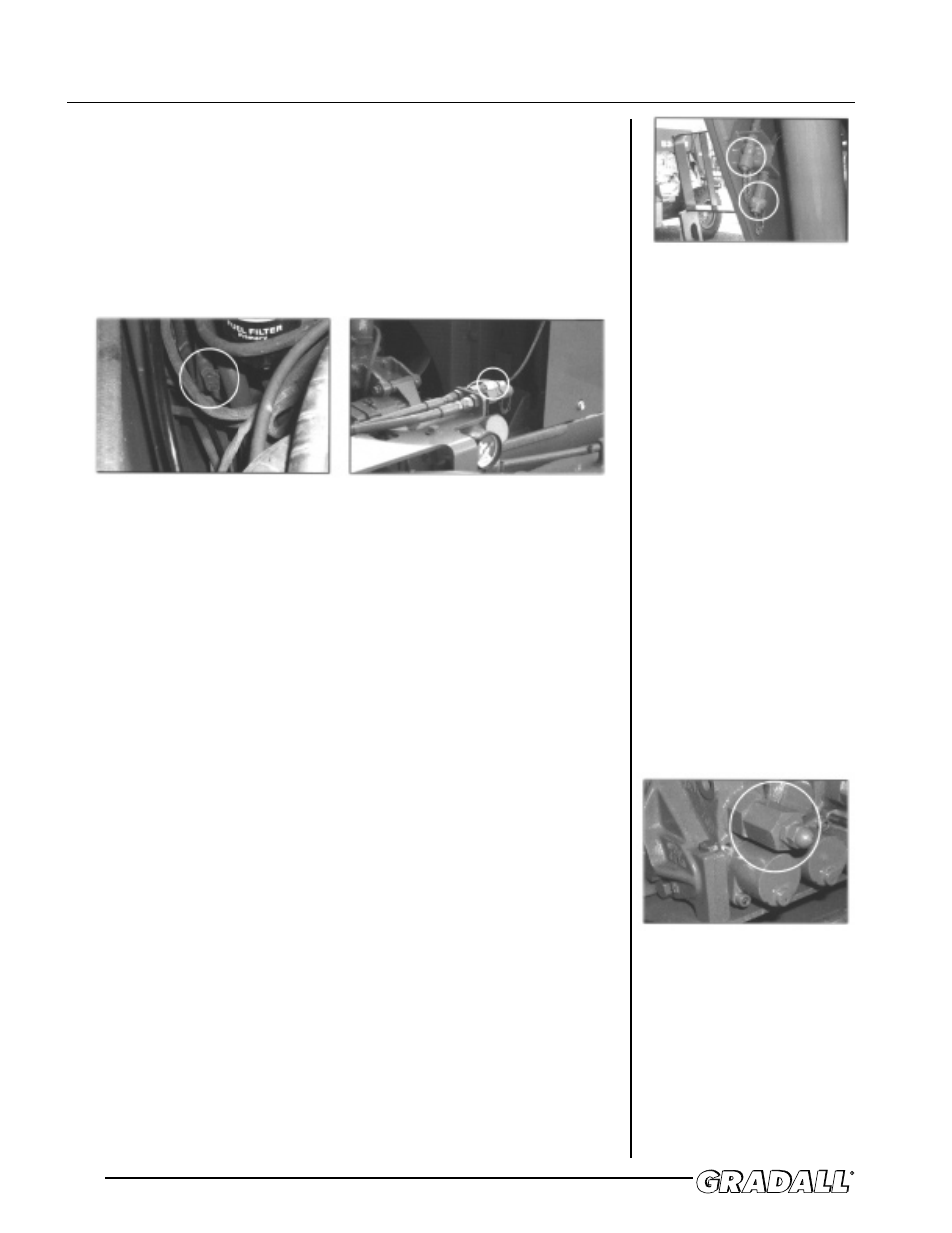
522, 524, 532C-6, 534C-6 and 534C-6T
MAIN IMPLEMENT TEST PORT
ALL OTHER MODELS
MAIN IMPLEMENT TEST PORT
BOOM-HEAD QUICK-DISCONNECT
FITTINGS
AUXILIARY RELIEF
NOTE!
The location of the main
implement test port varies by
machine vintage.