Main control valve pump relief, Ontrol, Alve – Gradall 534D-6T Service Manual User Manual
Page 265: Elief 6.0
F
ORM
N
O. 29813 •
I
MPLEMENT
C
IRCUIT
P
ERFORMANCE
C
HECKS (C & D Series Material Handlers)
M
AIN
C
ONTROL
V
ALVE
P
UMP
R
ELIEF
6.0
•
SET UP
1. Install a 10,000 PSI gauge, hose and adapter to the test port in
the outlet tube of the main implement pump. Make sure you can
see the gauge from the operator’s cab.
2. With the park brake engaged and the transmission in “Neutral”,
start the material handler. Move the Boom In/Out lever fully right
to extend the boom to the end of its stroke.
•
CHECK
1. With the engine running at full throttle (2500 RPM), observe
the pressure gauge.
2. The gauge should read:
522, 524, 532C-6, 534C-6, 522D, 524D, 534D-6 ................. 3000 ± 100 PSI
534C-9, 534C-10, 534D-9, 534D-10 ................................. 3200 ± 100 PSI
544C-10, 544D-10 ....................................................... 3600 ± 100 PSI
•
ADJUST
1. Before attempting any adjustment, you must switch the engine
off! Also, make sure the park brake is still engaged.
2. The main pump relief is located in the inlet side of the main
control valve, located under the operator’s seat.
3. If necessary, loosen the pump relief valve locknut.
4. Turn the adjusting screw clockwise to increase pressure; counter-
clockwise to reduce pressure.
5. Tighten the locknut and re-test for proper pressure.
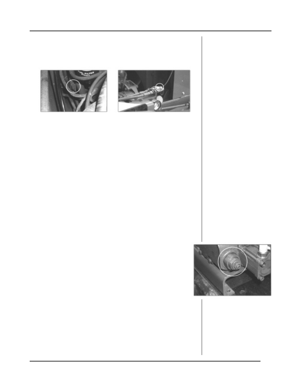
522, 524, 532C-6, 534C-6 and 534C-6T
MAIN IMPLEMENT TEST PORT
ALL OTHER MODELS
MAIN IMPLEMENT TEST PORT
MAIN PUMP RELIEF VALVE
NOTE!
The location of the main
implement test port varies by
machine vintage.