Hale TPM Sistem User Manual
Page 3
Hale Products Inc. • A Unit of IDEX Corporation • 700 Spring Mill Avenue • Conshohocken, PA 19428
Phone: 610/825-6300 • Fax: 610/825-6440 • 800-220-4253 • www.haleproducts.com
3
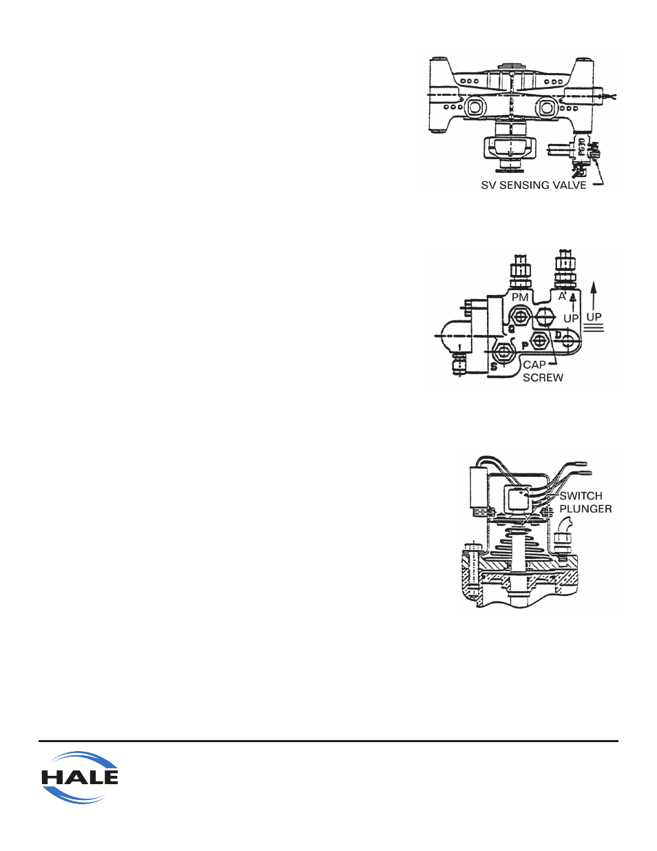
PG30 RELIEF VALVE & SENSING VALVE ASSEMBLY
You must find an open discharge pad on the midship pump to
mount the PG30 Relief Valve and Sensing Valve Assembly. One
typical location is shown in Figure 3. Any available opening
can be used including any of the “four-bolt” openings on the top
of the pump if space permits. In deciding which opening to use,
remember that a 3” pipe line directing the water to the ground
must be threaded into the PG30 outlet flange. Note that the PG30
relief valve can be rotated into four different positions on any
given pump discharge opening.
Once you have determined the proper outlet and orientation,
mount the PG30 relief valve using a greased gasket (046-0050-
00-0) and, attach using the two “C” Washers (097-0440-00-0)
and four 7/16-14 x 1-1/2” I.G. hex head capscrews (018-1814-
02-0). Tighten to 48 ft. lbs. torque.
The sensing valve (bolted to the PG30 relief valve) must now be
checked for proper orientation. Regardless of where the PG30
is mounted on the pump, the sensing valve must be bolted to a
boss on the SIDE of the relief valve, NOT the top or bottom. In
addition, the connections marked “A” and “PM” must point “UP”
as shown in Figure 4. The sensing valve is moved or rotated
by removing the 7/16” capscrew shown, and reinstalling after
it is in the proper orientation. NOTE that this “UP” position is
CRITICAL to the proper operation of the TPM System.
Attach the switch/flasher bracket to the PG30 relief valve cover
as shown in Figure 5. This is done by removing two of the cover
capscrews opposite each other. Reinstall the capscrews and
washers securing the switch bracket as shown. Adjust the bolts in
the side of the bracket until the switch plunger is depressed in the
normal position shown. Tighten all bolts securely.
1.
2.
3.
4.
FIGURE 3
FIGURE 4
FIGURE 5