Bryant DURAPAC 580F User Manual
Page 39
—
39
—
V. ECONOMI$ER IV ADJUSTMENT
Refer to Optional EconoMi$er IV section on page 15.
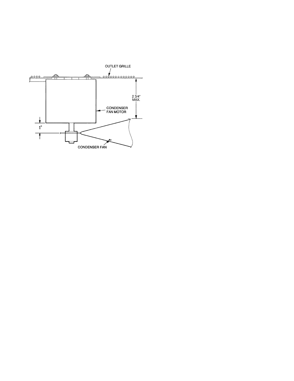
VI. CONDENSER-FAN ADJUSTMENT (Fig. 39)
Shut off unit power supply. Remove condenser-fan assembly
(grille, motor, and fan) and loosen fan hub setscrews. Adjust
fan height as shown in Fig. 39. Tighten setscrews and
replace condenser-fan assembly.
VII. REFRIGERANT CHARGE
Amount of refrigerant charge is listed on unit nameplate
(also refer to Table 1). Compressor must run a minimum of
10 minutes before adjusting or checking charge.
Unit panels must be in place when unit is operating during
charging procedure.
A. No Charge
Use standard evacuating techniques. After evacuating sys-
tem, to 500 microns, weigh in the specified amount of refrig-
erant. (Refer to Table 1.)
B. Low-Charge Cooling
Using Cooling Charging Charts, Fig. 40-43, vary refrigerant
until the conditions of the appropriate chart are met. Note
the charging charts are different from type normally used.
Charts are based on charging the units to the correct super-
heat for the various operating conditions. Accurate pressure
gage and temperature sensing device are required. Do not
use pocket type thermometers for measuring surface temper-
atures as they are not designed for this type of measure-
ment. Connect the pressure gage to the service port on the
suction line. Mount the temperature sensing device on the
suction line and insulate it so that outdoor ambient tempera-
ture does not affect the reading. Indoor-air cfm must be
within the normal operating range of the unit.
C. To Use Cooling Charging Chart
Take the outdoor ambient temperature and read the suction
pressure gage. Refer to chart to determine what suction tem-
perature should be. If suction temperature is high, add
refrigerant. If suction temperature is low, carefully recover
some of the charge. Recheck the suction pressure as charge
is adjusted.
EXAMPLE: (Fig. 42)
Outdoor Temperature . . . . . . . . . . . . . . . . . . . . . . . . . . . 85 F
Suction Pressure . . . . . . . . . . . . . . . . . . . . . . . . . . . . . .80 psig
Suction Temperature should be . . . . . . . . . . . . . . . . . . . 76 F
(Suction Temperature may vary 5 F.)
VIII. FLUE GAS PASSAGEWAYS
To inspect the flue collector box and upper areas of the heat
exchanger:
1. Remove the combustion blower wheel and motor
assembly according to directions in Combustion-Air
Blower section on page 39.
2. Remove the flue cover to inspect the heat exchanger.
3. Clean all surfaces as required using a wire brush.
IX. COMBUSTION-AIR BLOWER
Clean periodically to assure proper airflow and heating effi-
ciency. Inspect blower wheel every fall and periodically during
heating season. For the first heating season, inspect blower
wheel bimonthly to determine proper cleaning frequency.
To access burner section, slide the sliding burner partition
out of the unit.
To inspect blower wheel, shine a flashlight into draft hood
opening. If cleaning is required, remove motor and wheel as
follows:
1. Slide burner access panel out.
2. Remove the 7 screws that attach induced-draft motor
housing to vestibule plate (Fig. 44).
3. The blower wheel can be cleaned at this point. If ad-
ditional cleaning is required, continue with Steps 4
and 5.
4. To remove blower from the motor shaft, remove
2 setscrews.
5. To remove motor, remove the 4 screws that hold the
motor to mounting plate. Remove the motor cooling
fan by removing one setscrew. Then remove nuts that
hold motor to mounting plate.
6. To reinstall, reverse the procedure outlined above.
X. LIMIT SWITCH
Remove blower access panel (Fig. 7). Limit switch is located
on the fan deck.
XI. BURNER IGNITION
Unit is equipped with a direct spark ignition 100% lockout
system. Integrated Gas Unit Controller (IGC) is located in the
control box (Fig. 11). The IGC contains a self-diagnostic LED
(light-emitting diode). A single LED on the IGC provides a
visual display of operational or sequential problems when the
power supply is uninterrupted. When a break in power occurs,
the IGC will be reset (resulting in a loss of fault history) and
the indoor (evaporator) fan ON/OFF times will be reset. The
LED error code can be observed through the viewport. During
servicing refer to the label on the control box cover or Table 34
for an explanation of LED error code descriptions.
If lockout occurs, unit may be reset by interrupting power
supply to unit for at least 5 seconds.
Fig. 39 — Condenser-Fan Adjustment