Fig. 31 — economi$er iv control – Bryant DURAPAC 580F User Manual
Page 19
—
19
—
Indoor Air Quality (IAQ) Sensor Input
The IAQ input can be used for demand control ventilation
control based on the level of CO
2
measured in the space or
return air duct.
Mount the accessory IAQ sensor according to manufacturer
specifications. The IAQ sensor should be wired to the AQ and
AQ1 terminals of the controller. Adjust the DCV potentiome-
ters to correspond to the DCV voltage output of the indoor air
quality sensor at the user-determined set point. See Fig. 32.
If a separate field-supplied transformer is used to power the
IAQ sensor, the sensor must not be grounded or the
EconoMi$er IV control board will be damaged.
Exhaust Set Point Adjustment
The exhaust set point will determine when the exhaust fan
runs based on damper position (if accessory power exhaust is
installed). The set point is modified with the Exhaust Fan
Set Point (EXH SET) potentiometer. See Fig. 27. The set
point represents the damper position above which the
exhaust fans will be turned on. When there is a call for
exhaust, the EconoMi$er IV controller provides a 45 ± 15
second delay before exhaust fan activation to allow the
dampers to open. This delay allows the damper to reach the
appropriate position to avoid unnecessary fan overload.
Minimum Position Control
There is a minimum damper position potentiometer on the
EconoMi$er IV controller. See Fig. 27. The minimum damper
position maintains the minimum airflow into the building
during the occupied period.
When using demand ventilation, the minimum damper posi-
tion represents the minimum ventilation position for VOC
(volatile organic compound) ventilation requirements. The
maximum demand ventilation position is used for fully occu-
pied ventilation.
When demand ventilation control is not being used, the min-
imum position potentiometer should be used to set the occu-
pied ventilation position. The maximum demand ventilation
position should be turned fully clockwise.
Adjust the minimum position potentiometer to allow the
minimum amount of outdoor air, as required by local codes,
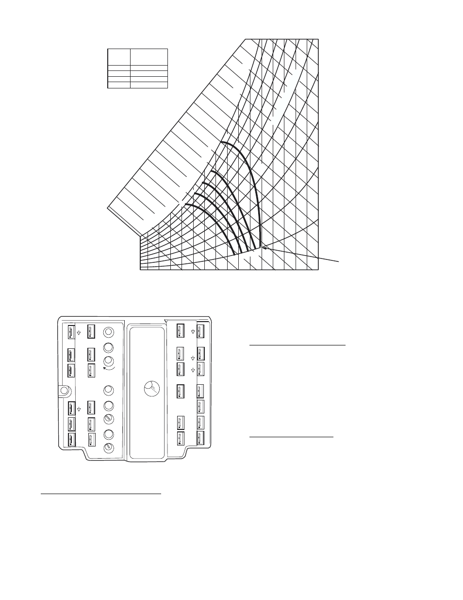
Fig. 30 — Enthalpy Changeover Settings
CONTROL
CURVE
A
B
C
D
CONTROL POINT
APPROX. °F (°C)
AT 50% RH
73 (23)
70 (21)
67 (19)
63 (17)
12
14
16
18
20
22
24
26
28
30
32
34
36
38
40
42
44
46
9
0
1
0
0
80
70
6
0
50
40
30
20
10
E
NT
HA
LP
Y
—
B
TU
P
E
R
PO
U
N
D
DR
Y A
IR
85
(29)
90
(32)
95
(35)
100
(38)
105
(41)
110
(43)
35
(2)
35
(2)
40
(4)
40
(4)
105
(41)
110
(43)
45
(7)
45
(7)
50
(10)
50
(10)
55
(13)
55
(13)
60
(16)
60
(16)
65
(18)
65
(18)
70
(21)
70
(21)
75
(24)
75
(24)
80
(27)
80
(27)
85
(29)
90
(32)
95
(35)
100
(38)
APPROXIMATE DRY BULB TEMPERATURE— °F (°C)
A
A
B
B
C
C
D
D
REL
A
T
IVE HU
M
IDIT
Y
(
%
)
HIGH LIMIT
CURVE
TR1
24 Vac
COM
TR
24
Vac
HOT
1
2
3
4
5
EF
EF1
+
_
P1
T1
P
T
N
EXH
2V
10V
EXH
Set
Set
2V
10V
2V
10V
DCV
DCV
Free
Cool
B
C
A
D
SO+
SR+
SR
SO
AQ1
AQ
DCV
Min
Pos
Open
Max
N1
Fig. 31 — EconoMi$er IV Control