Appendix i-a – Goulds Pumps 3910 11th ed. - IOM User Manual
Page 63
APPENDIX I-A
APPENDIX I- Installation and Disassembly Instructions for Goulds ANSI B15.1
Coupling Guards
A — All Power Ends Except Those with Optional Air Cooling Package . . . . . . . . 63
B — Power Ends with Optional Air Cooling Package . . . . . . . . . . . . . . . . . . 67
APPENDIX II - Dial Indicator (Rim-and-Face) Alignment Procedure . . . . . . . . . . 71
APPENDIX III - Removal and Assembly of Back Pull-Out Assembly . . . . . . . . . . 75
INSTALLATION AND DISASSEMBLY
INSTRUCTIONS FOR GOULDS ANSI B15.1
COUPLING GUARDS
(CASING MOUNT MOTOR SUPPORT ONLY)
!
The coupling guard used in an ATEX classified
environment must be constructed from a non-
sparking material.
All Power Ends Except Those Mounted with
Optional Air Cooling Package
s
!
WARNING
Before installation or disassembly of the coupling
guard is performed, the driver must be de-energized,
the driver controller / starter put in a locked-out
position and a caution tag placed at the controller /
starter indicating the disconnect. Replace coupling
guard before resuming normal operation of the pump.
ITT Industries - Goulds Pumps assumes no liability for
avoiding this practice.
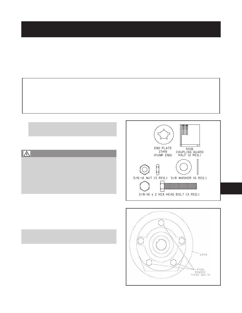
Simplicity of design allows complete assembly of the coupling
guard, including the end plate (pump end), in about fifteen
minutes. If the end plate is already in place, assembly can be
accomplished in about five minutes. Fig. I-A-1 shows the
coupling guard components.
INSTALLATION
NOTE: If end plate (pump end) is already installed,
make any necessary coupling adjustments and then
proceed to Step 7.
1.
Remove spacer portion of coupling. Refer to coupling
manufacturer’s instructions for assistance.
2.
If the coupling hub diameter is larger than the diameter
of the opening in the end plate (234B), remove the
coupling hub.
3.
Remove three thrust bearing end cover/bearing frame
screws (370N) as indicated in Fig. I-A-2.
3910-
11th IOM 5/08
63
Fig. I-A-1
Fig. I-A-2
8