Goulds Pumps 3410 - IOM User Manual
Page 18
LIFTING THE PUMP
s
!
WARNING
Pump and components are heavy. Failure to properly
lift and support the equipment could result in serious
physical injury, or damage to the pump(s). Steel-toed
shoes must be worn at all times.
The following instructions are for the safe lifting of your
pump.
The unit should be unloaded and handled by lifting equally
at four or more points on the baseplate. The lugs on the
upper half casing are designed for lifting the upper half
casing only.
HORIZONTAL
Bare Pump
1.
Using a nylon sling, chain, or wire rope, hitch around
both bearing housings. (See Fig. 4)
Pump, Base, and Driver
2.
Care must be taken to size equipment for unbalanced
loads which may exist if the driver is not mounted on
the base at the time of lifting. Driver may or may not
be mounted at the factory.
3.
Pump, base, and driver assemblies where the base
length exceeds 100 inches may not be safe to lift as a
complete assembly. Damage to the baseplate may
occur. If the driver has been mounted on the baseplate
at the factory, it is safe to lift the entire assembly. If
driver has not been mounted at the factory and the
overall baseplate length exceeds 100 inches, do not lift
entire assembly consisting of pump, base, and driver.
Instead, lift the pump and baseplate to its final
location without the driver. Then mount the driver.
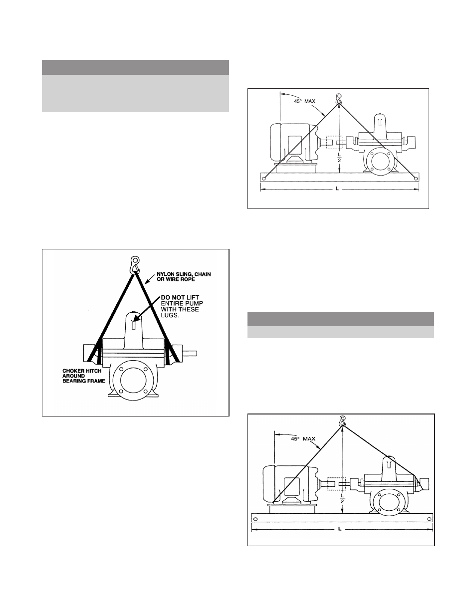
Bases supplied with lifting holes
Large bases are supplied with lifting holes in the sides or
the ends of the base. (See Fig. 5)
Using ANSI/OSHA Standard “S” hooks, place the “S” hooks in
the holes provided in the four corners of the base. Be sure the
points of the hooks do not touch the bottom of the pump base.
Attach nylon slings, chains, or wire rope to the “S” hooks. Size
the equipment for the load so the lift angle will be less than 45°
from the vertical.
Bases supplied without lifting holes
Place one sling around the outboard bearing housing.
s
!
WARNING
Do not use lugs on top half of casing.
Place the remaining sling around the back end of the driver as
close to the mounting feet as possible. Make certain sling will not
damage housing cover or conduit boxes.
Join the free ends of the slings together and place over the lifting
hook. Use extreme care when positioning sling under the driver
and bearing housing so it cannot slip off (See Fig. 6).
16
3410 IOM 1/2010
Fig. 4
Fig. 5
Fig. 6