5 installation/commissioning, 6 maintenance/cleaning – Barksdale UQS7 User Manual
Page 3
5 Installation/Commissioning
Electrical connection is to be carried out dependent on the type of switch (see type label)
according to the chart below. Wrong assignment of the connections may cause malfunctions or
incorrect switch outputs.
DANGER
The sensor must be installed and operated only by authorized persons.
Only install or uninstall the sensor when deenergized (electrically and hydraulically/pneumatically).
Pressure connection and electrical connection must be carried out by trained or instructed
personnel according to state-of-the-art standards. The sensor must only be installed in systems
where the maximum pressure P
max
or the maximum temperature T
max
is not exceeded (see data
sheet).
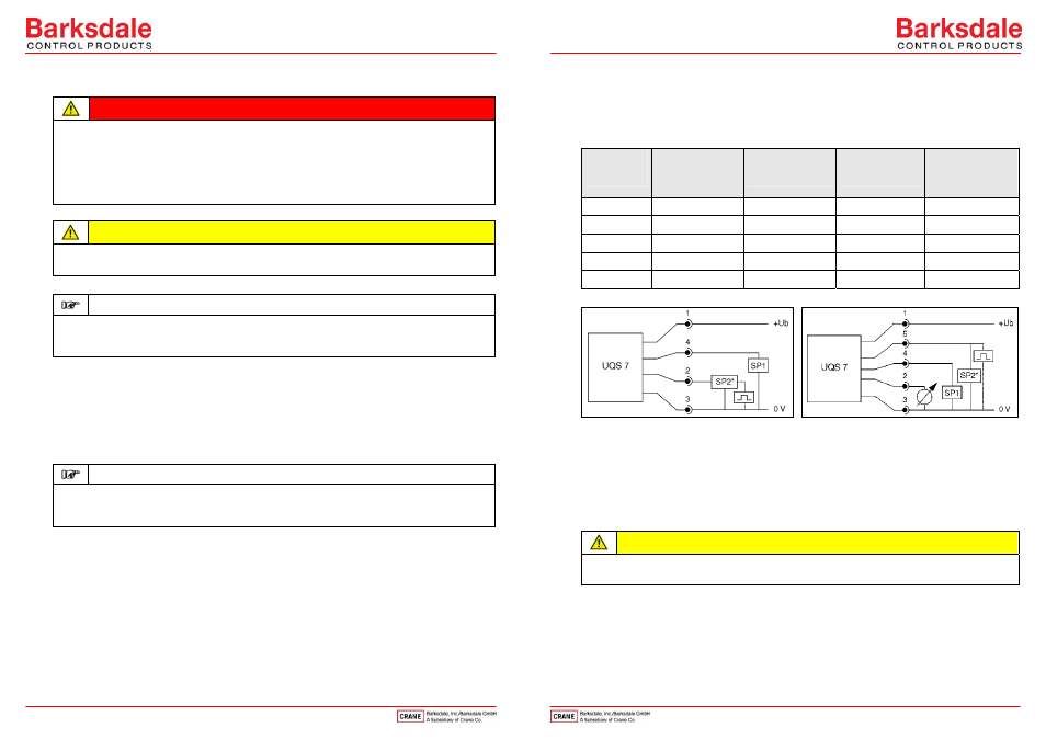
Connection Chart/Connection Scheme
CAUTION
Cover and bottom of the device are a function unit. Changing the parts may cause measuring
errors or malfunction. See serial number inside the cover.
IMPORTANT
For wall mounting the back of the device has to be mounted with appropriate screws. By loosening
the both backside screws the unit is rotable in steps of 90° and can also be mounted separately
(recommended in case of strong vibrations).
The electrical connection (power supply, analog output and switching contacts) acc. to
connection chart.
Connect the fittings with the pipe. For sealing use the attached Klingersil seals only.
Mounting of the device according to the flow direction (arrow on the back).
Connect pipe and fittings manually.
Tighten both fittings against one another.
IMPORTANT
During operation air bubbles in the system may affect measuring.
Please flush the system after installation or ventilation with >3 l/min; 0.8 gpm. The operating
pressure must not exceed 1 bar.
Plug
M 12x1
4/5-pin
Version with
2 switching outputs
Version with
2 switching outputs
and 1 analog output
Version with
1 switching output
and 1 pulse output.
Version with 1
switching output,
1 pulse output and
1 analog output
Pin 1
+Ub (15...32 V DC)
+Ub (15...32 V DC)
+Ub (15...32 V DC)
+Ub (15...32 V DC)
Pin 2
SP2 (0.5 A max.)
Analog
Pulse output
Analog
Pin 3
0 V
0 V
0 V
0 V
Pin 4
SP1 (0.5 A max.)
SP1 (0.5 A max.)
SP1 (0.5 A max.)
SP1 (0.5 A max.)
Pin 5
SP2 (0.5 A max.)
Pulse output
SP2* = pulse output
6 Maintenance/Cleaning
Maintenance
The flow sensor requires no maintenance.
Cleaning
CAUTION
The plastic film keys may be damaged by the use of unsuitable cleaning agents. Do not use any
cleaning agents containing solvents or abrasive additives.
5
4