About the interface – Pathway #8721, 8723, 8725, 8741, 8743, 8745 User Manual
Page 2
The Gray Interfaces 24 and 48 channel decoders
have been designed to permit easy, economical
upgrades to older lighting control systems with
analog dimmers. Standard input protocols are USITT
DMX-512 or AMX-192, or Strand D54.
A few simple steps are required to prepare your
interface unit for operation.
First, assemble your mating cables and ensure that
they conform to the connector pinouts as shown on
page 3. Plug the cable from your lighting control
board into the input connector on the rear panel of
the decoder unit. Note that AMX or DMX input
models include “in” and “thru” connectors,
whereas AMX and DMX input models only have “in”
connectors. The 25-pin output connector(s) of the
decoder unit wire directly to the dimmers’ analog
inputs.
Note - Unless otherwise ordered, all decoder units
are shipped with a factory default output
configuration of 0 to +10VDC. For other outputs,
refer to the configuration instructions on page 4.
Next set the starting address of the first output signal
using the three rotary address select switches.
Then, refer to the DIP Switch Settings on page 4. The
shaded settings are factory defaults.
Now apply power to the decoder unit by plugging
the cord from the power supply into the power jack
on the rear of the box, and plug the power cube
into a 120V outlet (the decoder can be left
powered up all the time, current draw is minimal). If
the microprocessor is operating properly, the
“POWER” LED on the front panel should illuminate.
Turn your control board on - the “DATA” LED will
illuminate if the decoder unit is receiving a valid
data signal. Now run some dimmers up to verify that
the decoder is working.
Note that in test mode (DS2 on) dimmers may be
turned on individually without the use of a control
board. Simply dial up the desired dimmer number
on the rotary address switches.
ABOUT THE INTERFACE
ABOUT THE INTERFACE
2
SETUP INSTRUCTIONS
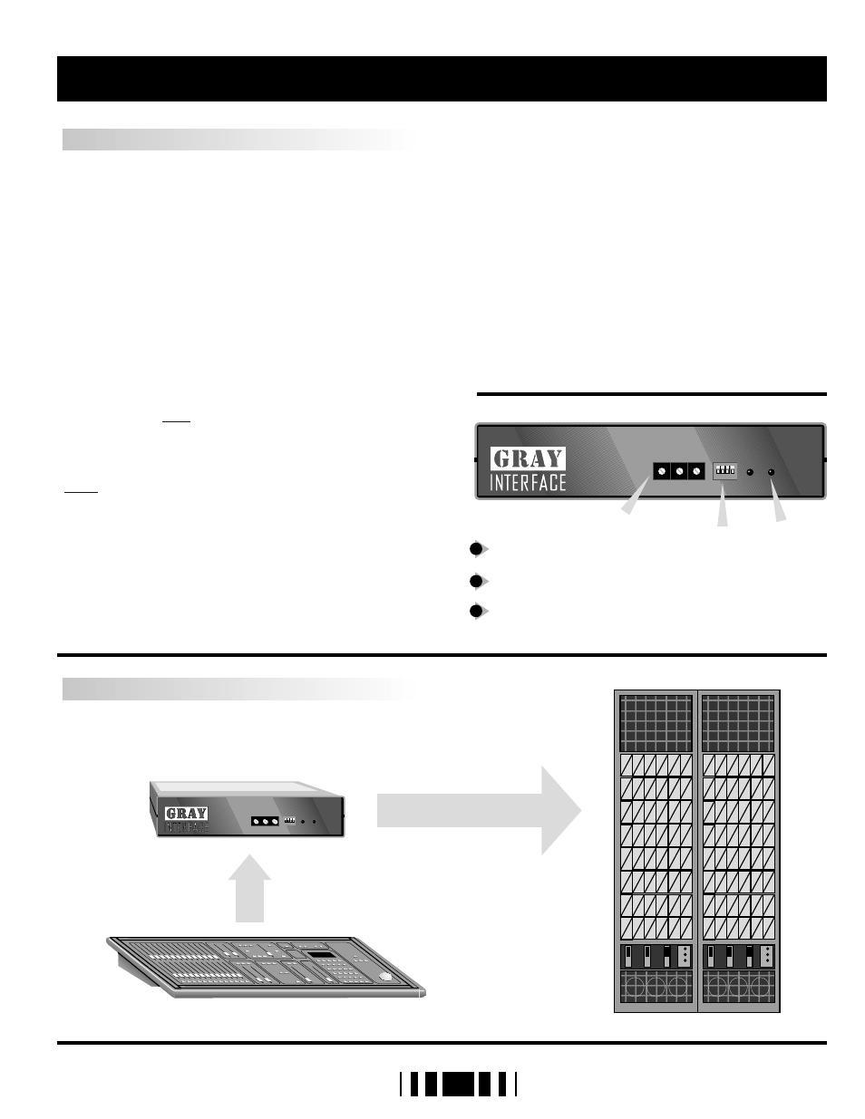
SYSTEM LAYOUT
Address select switches
Mode select DIP switches
LED indicators ( power and data )
1
2
3
X 100 X 10
X 1
made in Canada
address select
mode
pow
e
r
da
ta
4
3
2
1
1
2
3
4 5 6
7
8
90
1
2
3
4 5 6
7
8
90
1
2
3
4 5 6
7
8
90
1
2
3
X 100 X 10
X 1
made in Canada
address select
mode
pow
e
r
da
ta
4
3
2
1
1
2
3
4 5 6
7
8
90
1
2
3
4 5 6
7
8
90
1
2
3
4 5 6
7
8
90
D M X D e c o d e r
D M X D e c o d e r