Pathway #4813, 4814, 4815 DMX/RDM Installation Splitters User Manual
Dmx/rdm installation splitter
MOUNTING
OPERATIONAL PHILOSOPHY
An essential component of any DMX512
distribution
system,
DMX/RDM
Installation
Splitters permit star wiring in systems required
to support E1.20 Remote Device Management
(RDM), while fully isolating and protecting
connected equipment from harmful electrical
faults of up to 2500V.
DMX512 standards require that DMX devices be installed
in a daisy chain, with no tees, wyes or stars in the DMX
wiring. However, site conditions may make star wiring
desirable or even mandatory.
A DMX/RDM Installation Splitter provides up to 3
eDIN modules, for a total possible 12 output branches.
Each branch acts electrically as its own entity, unaffected
by faults on other branches of the star. Opto-isolation
prevents ground loops or damage to control consoles by
fault voltages on DMX lines.
The RDM standard requires that splitters be ca-
pable of half-duplex bi-directional communication. The
standard stipulates that no more than four RDM-enabled
splitters may be daisy-chained together.
DMX/RDM Installation Splitters transparently han-
dle all RDM data and meet the timing constraints of the
standard. Do not install RDM responder devices between
the Installation Splitter and the console.
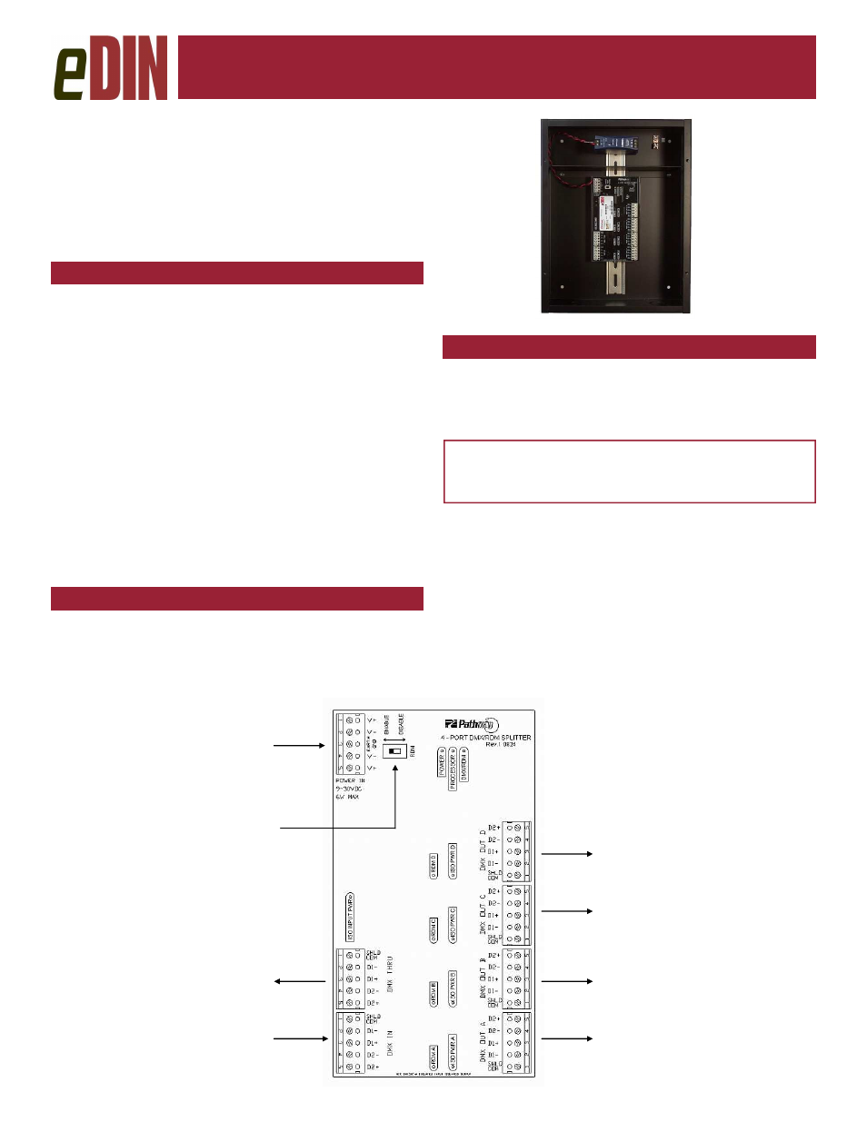
CONNECTIONS
DMX/RDM Installation Splitters are delivered with the
power supply pre-wired to the first module, and with all
required wiring daisy-chained to any additional cards.
The following connections must be done on-site.
DMX/RDM Installation Splitter
DMX/RDM Installation Splitter
DMX/RDM Installation Splitter
DMX/RDM Installation Splitter
Installer’s Guide
Installer’s Guide
Installer’s Guide
Installer’s Guide
Models 4813, 4814, 4815
Model 4813
DMX/RDM Installation Splitters are designed for indoor
use in a dry location. Mount the Installation Splitter to the
wall with appropriate fasteners. Run conduit into the box
through the knockouts provided, ensuring that line voltage
wiring is kept inside the barriered power supply section.
WARNING : DMX input/output ports must be
connected to low-voltage data lines only. Do not
connect DMX ports to high voltage sources.
DMX IN is wired to the control console output or to an-
other DMX source.
DMX OUT connectors are wired to the remote DMX de-
vices, RDM responders or to receptacles for end equip-
ment receiving the console signal. These may be dim-
mers, scrollers or moving lights, for example.
POWER: With the power off, make the appropriate con-
nections to Ground, Neutral and Line screws of the power
supply in the barriered section at the top of the cabinet.
From power supply
To other eDINs or
DMX equipment
From console.
Do not install other
RDM equipment be-
tween console and
eDIN module
To DMX/RDM equipment
To DMX/RDM equipment
To DMX/RDM equipment
To DMX/RDM equipment
RDM disable switch