Power Soak 35351 Skewer Soak INstallation Manual User Manual
Page 14
10
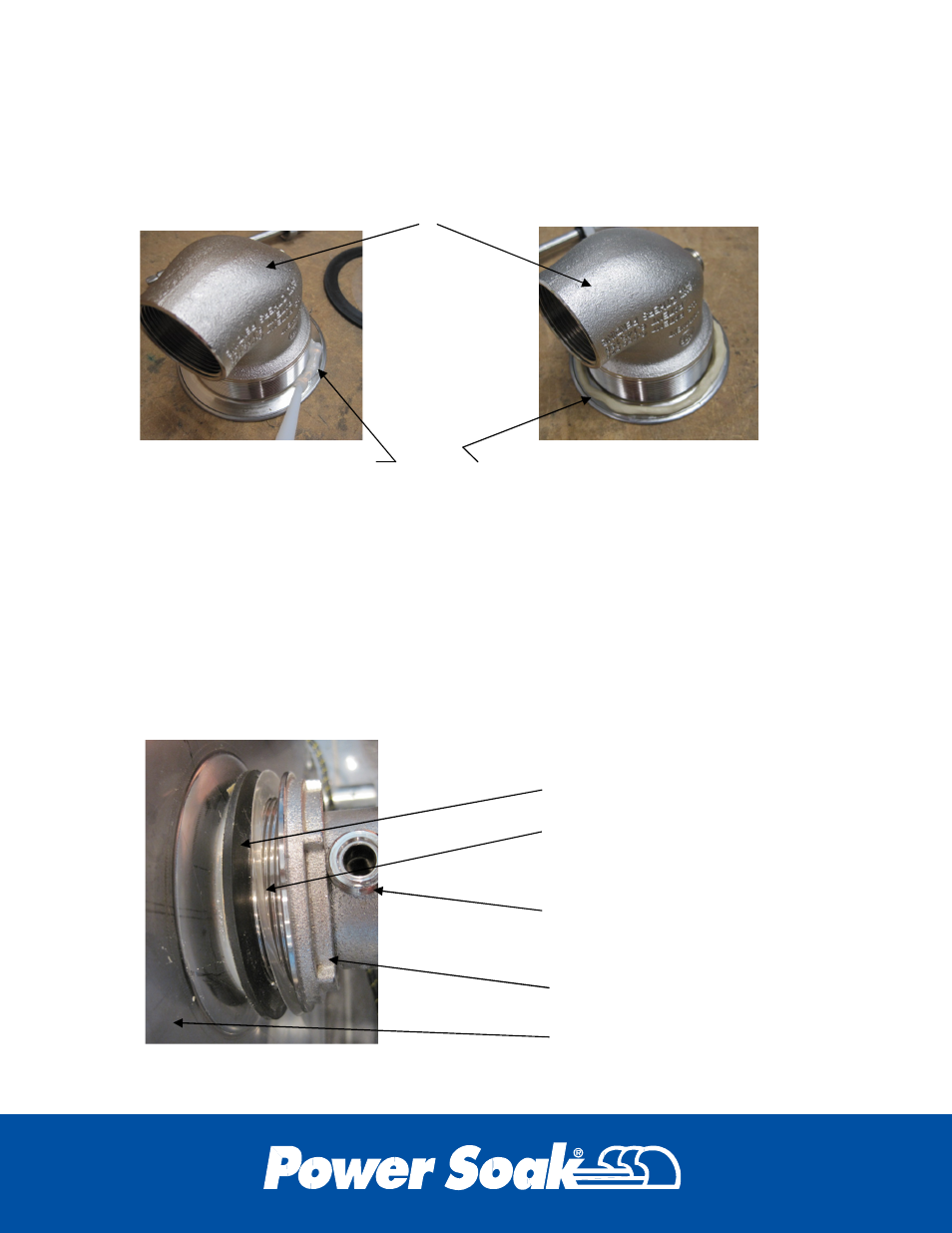
Bottom Drain
Each drain flange must be sealed to its mating surface in the sink. Apply a
generous bead of clear silicone sealant (supplied with the machine) around
the lip of the drain body or form a ring of “plumber’s putty” and place it on
the lip of the drain body.
The drains with built-in valves will be oriented with the handle connection
toward the front of the sink. From inside the sink, insert the drain through
the drain hole and seat the flange against the sheet metal surface of the
tank. When using “plumber’s putty”, be sure that the ring of putty
compresses to where the rim of the drain actually touches the sheet metal
surface of the sink. If the drain does not touch the sink it will work loose
and leak as the putty compresses over time.
From the outside of the tank place the rubber vibration ring over the
threaded body of the drain followed by the Teflon ring and then the drain
nut. Tighten the nut “hand tight” until the handle is installed.
DRAIN BODY
CLEAR SILICONE SEALANT
RUBBER VIBRATION RING
TEFLON RING
FLANGE NUT
HANDLE CONNECTION
ORIENTED TOWARD THE
FRONT OF THE MACHINE.
BOTTOM OF SINK (Sink is laying
on its back side in this illustration)
FORMED RING OF PLUMBER’S PUTTY