Power Soak 34773 ps-200/201 Service Manual User Manual
Page 12
9
Triac (Thyristor or Solid-State Relay)
The Triac is a three terminal semiconductor for controlling current in either direction. The
Triac in the Power Soak is used similar to a contactor. When a gate voltage is applied from
the UPM (similar to coil voltage on a mechanical Contactor Relay), the Triac conducts
(closes) through the power terminals. On a single phase Control Panel, there are two
Triacs, one for the Heater, the other for the Motor. Terminals 2 and 3 on each Triac are
supplied with incoming voltage. On the top of these Triacs, they are labeled M1 (motor leg
1) and H1 (heater leg 1). On a three phase Control Panel there are four Triacs, two for the
Heater, and two for the Motor. Two are labeled identically to a single phase Panel. The two
others are labeled M3 (motor leg 3) and H3 (heater leg 3). Terminals 2 and 3 on each Triac
are supplied with incoming voltage. To test the Triac, first verify the input voltage to the
Triac. An LED on the Triac board signals whether the gate voltage has been applied by the
UPM. If the light is on, the Triac should be closed, and terminal 1 of the Triac should be
supplying power to the respective device. If the LED is off, there should be virtually no
current on the output side of the Triac.
Contactor
If there is a 20v-28v across the coil and the contactor does not pull in, the contactor is
defective. If there is input voltage across terminals L1 and L2 (also L1-L3 and L2-L3, if
three phase) and the contactor is pulled in, but no voltage across terminals T1 and T2 (also
T1-T3 and T2-T3, if three phase), the contactor is defective.
Heater Element
The heater in a Power Soak sink is rated at 7000 watts. To check operations of the heat
element, first turn the power off at the breaker. Disconnect the H2 wire from terminal H2
and the H1 wire from the triac H1 (and H3 wire from H3 triac, if 3 phase) from the Control
Panel. Check each heater lead to ground for short. They all should be open to ground.
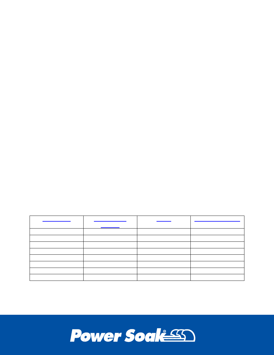
Check resistance between each of the combinations of the chart below.
Connection
Heater Rated
Voltage
phase
Resistance (ohms)
H1-H2
208-230
1
7.56
H1-H2
208-230
3
15.12
H2-H3
208-230
3
15.12
H1-H3
208-230
3
15.12
H1-H2
460
1
32.91
H1-H2
460
3
65.83
H2-H3
460
3
65.83
H1-H3
460
3
65.83
The heater should be within a 10% variance of the value of the chart.
If the reading varies significantly from the chart above, the heater may be defective, or
there may be a broken wire or loose connection. Electrically, the Heater is three separate
elements, each of 2333 watts. When replacing, note how the existing Heater is wired, and
refer to the schematic when wiring new heater.