Metpar Phenolic User Manual
Page 4
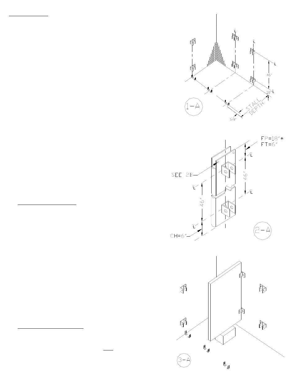
STEP 1
STEP 1 -- Layout
Layout
A. Mark the centerline of each stile location from the back wall.
The centerline of the stile is 5/8” less than the overall
dimension shown. Phenolic = 3/8” less. Measure out at each
end of overall distance from first stall to last in line.
B. Mark the centerline of all top and bottom wall brackets.
Adjust if possible to locate in mortar joints. Caution: if doors
use s/s surface hinges, you may need to raise or lower the
wall brackets on 2”, 3” and 4” stiles to avoid any conflict with
the door hinges.
C. From the side wall measure along the centerline of the stiles
to locate the floor fasteners, to be located 1” in from each
end of each pilaster. FP stiles at 2” and 3” use only one (1)
floor mounting. FT and CH stiles at 2”, 3”, 4” and 5” use only
one (1) mounting.
D. Mark all bracket holes to be drilled using brackets as
templates.
E. Drill ¼” holes for wall brackets.
F. Drill holes for floor fastenings, ¼” for FP500 or ¾” for
FT700.
G. Insert plastic anchors into holes (see detail 4A).
H. Secure wall brackets with #12 x 2 ½” screws. Pilaster
brackets have a wider space between the legs because a stile
is thicker than a panel.
STEP 2
STEP 2 -- P
Prepare Stiles
repare Stiles
A. Locate the U-brackets against the pilaster using the center-
line dimensions. For Plastic and Phenolic, a 1-ear or 2-ear
bracket will be used behind the pilaster. For FP500 and
FT700 measure downward* from the top. For CH700,
measure upward from the bottom of the stile. Fasten the
brackets in place with sheet metal screws.
B. On FP500 metal stiles, drill 2 pilot holes through the top
back of the stile for headrail screws.
C. Extend the leveling bolt (jackstuds) from the top of FP500
stiles to the bottom of the leveling bolthead to 82”.
D. Slide the stainless steel plinth onto the stile.
*Note: Measure downward 18” for powder Shield or Stainless
Steel. Measure 16½” downward for Plastic Laminate or Phenolic.
STEP 3
STEP 3 -- POSITION PANEL
POSITION PANEL
A. Set the panel onto some type of support 12” high in position
to hold the panel.
B. Set the panel into the wall brackets BUT
BUT do not fasten the
panel to the wall brackets yet.
Page 3