Pumptec 356U SERIES User Manual
Page 8
8
Version 061113
Pumptec Operating Instructions and Parts Manual
PUMP SERIES 348U | 350U | 356U
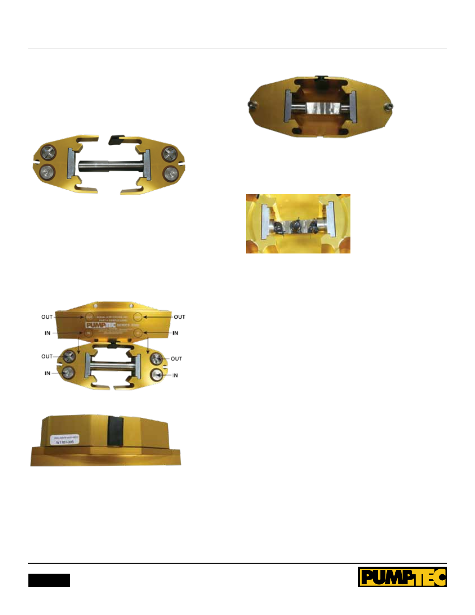
9. Adjust plunger slot position towards center and have slot
facing work surface. Replace all valves, O-rings and white wash-
ers. Refer to image and manifold label to understand proper
orientation.
Figure 6
10. Place manifold on top of plunger and head assembly. It may
be necessary to move heads on plunger to have valves align
with valve pockets on manifold. be careful to not lose the white
washers in the manifold during reassembly.
IMPortANt:
It is imparative the alignment of OUT/In
ports coincide with valves as indicated in Figure 7.
PROPER AlIgnMEnT
Figure 7
11. Turn assembly over and place shorter bolt and washer
assembly into heads and tighten finger tight. DO nOT tighten
completely at this time.
Figure 8
12. Install black grease from included packet into corners and
center of plunger slot as shown.
Figure 9
13. Mount pump back onto motor and tighten mounting bolts
to 14 in/lbs. of torque. Tighten head bolts to 14 in/lbs. of
torque.
LUBriCAtiON
Apply 1.5 oz of suppliers black grease to the corners and center
of plunger slot at the time of service.
StorINg
For extended storing, or between use in cold climates, drain all
pumped liquids from pump and flush with antifreeze solution
to prevent freezing and damage to the pump. DO nOT RUn
PUMP WITH FROZEn lIQUID.
Note:
Each system’s maintenance cycle will be unique. If
system performance decreases, check immediately. If no wear
at 500 hours, check again at 1000 hours and each 500 hours
until wear is observed. Valves typically require changing every
seal change. Duty cycle, temperature, quality of pumped liquid
and inlet feed conditions all effect the life of a pump’s wear
parts and service cycle.
Note:
Remember to service the regulator/uploader at each
seal servicing and check all system accessories and connections
before resuming operation.