Pumptec 356U SERIES User Manual
Page 7
7
Version 061113
Pumptec Operating Instructions and Parts Manual
PUMP SERIES 348U | 350U | 356U
MAINteNANce
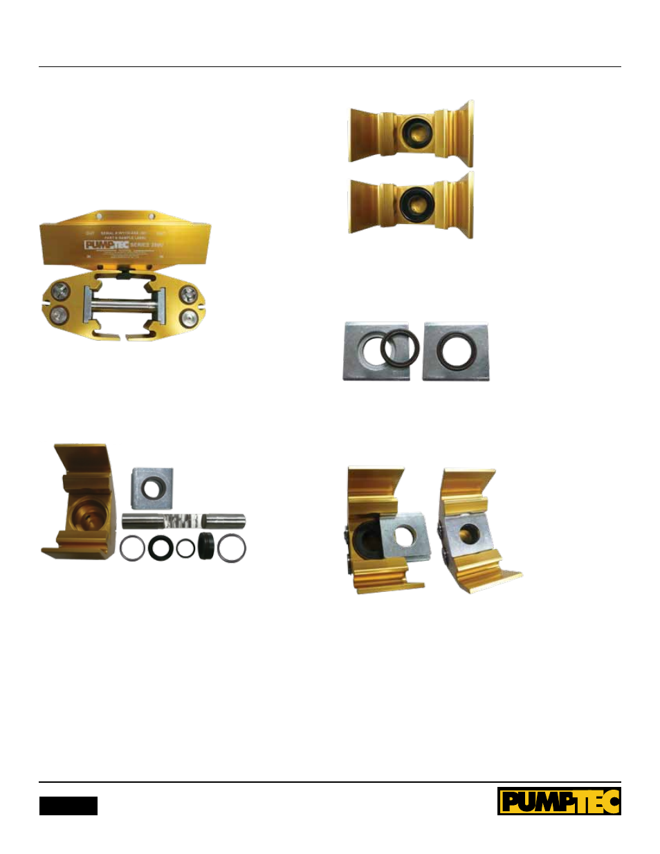
DISASSEMblY AnD REASSEMblY
InSTRUCTIOnS (Refer to Schematic)
1. Remove pump from motor using a 3/16” hex wrench for
Model 348U, and use 5/16” hex wrench for Model 350U and
356U. Remove bolts at each end of pump. Turn pump over so
manifold is facing upward. Place manifold to side as a reference
for reassembly.
Figure 1
2. Holding each head, pull them apart to remove plunger.
Remove retaining plate from pump head. Remove internal seal
parts with finger. Discard parts, keeping the head and retainer
plate.
Figure 2
3. Clean the head with a rag or towel inspect for damage or
excess corrosion. If the head is damaged, do not rebuild. note
the order and orientation of repair parts prior to installation.
4. Place one O-ring support, u-cup and u-cup support ring into
bore. Verify that u-cup support ring is flush with top of u-cup.
Place retainer O-ring into recessed area around top of bore.
Place guide O-ring around guide and lightly grease. Press guide
with O-ring installed into bore.
Figure 3
5. Place vacuum seal O-ring around vacuum seal. lightly grease
O-ring and press into recess in retaining plate. be careful to ap-
ply even pressure and eliminate bulges in O-ring.
Figure 4
6. grease edge of retaining plate and slide into place. If large re-
tainer O-ring dislodges, do not slide plate, but push O-ring back
into place before sliding into place completely.
Figure 5
7. Repeat the previous steps 3-5 with the other head.
8. lightly grease the plunger with provided grease in small clear
tube. Slide plunger into one head assembly and then slide the
other head onto plunger. Place head and plunger assembly on
work surface with valves facing upward.