8 bottom panel connectors, 1 lan connection, Ottom – IEI Integration POC-17i_19i-Series_IEI User Manual
Page 48: Anel, Onnectors, Figure 3-16: arm mounting retention screw holes
POC-17i/19i Series
Page 36
NOTE:
When purchasing the arm please ensure that it is VESA compliant and that
the arm has a 100 mm interface pad. If the mounting arm is not VESA
compliant it cannot be used to support the POC-17i/19i Series flat panel
PC.
Step 2:
Once the mounting arm has been firmly attached to the surface, lift the flat panel
PC onto the interface pad of the mounting arm.
Step 3:
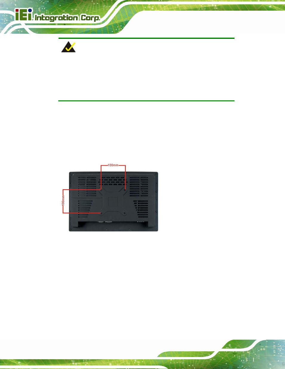
Align the retention screw holes on the mounting arm interface with those in the
flat panel PC. The POC-17i/19i Series arm mount retention screw holes are
Figure 3-16: Arm Mounting Retention Screw Holes
Step 4:
Secure the flat panel PC to the interface pad by inserting four retention screws
through the bottom of the mounting arm interface pad and into the flat panel PC.
3.8 Bottom Panel Connectors
3.8.1 LAN Connection
There are two external RJ-45 LAN connectors. The RJ-45 connector enables connection
to an external network. To connect a LAN cable with an RJ-45 connector, please follow
the instructions below.