Step 6: so-dimm installation, Step 7: wi-fi module installation (optional) – IEI Integration ECN-581A-R10-D5251 User Manual
Page 5
ECN-581A-D5251/HM551 QIG IEI Technology Corp. Page 5
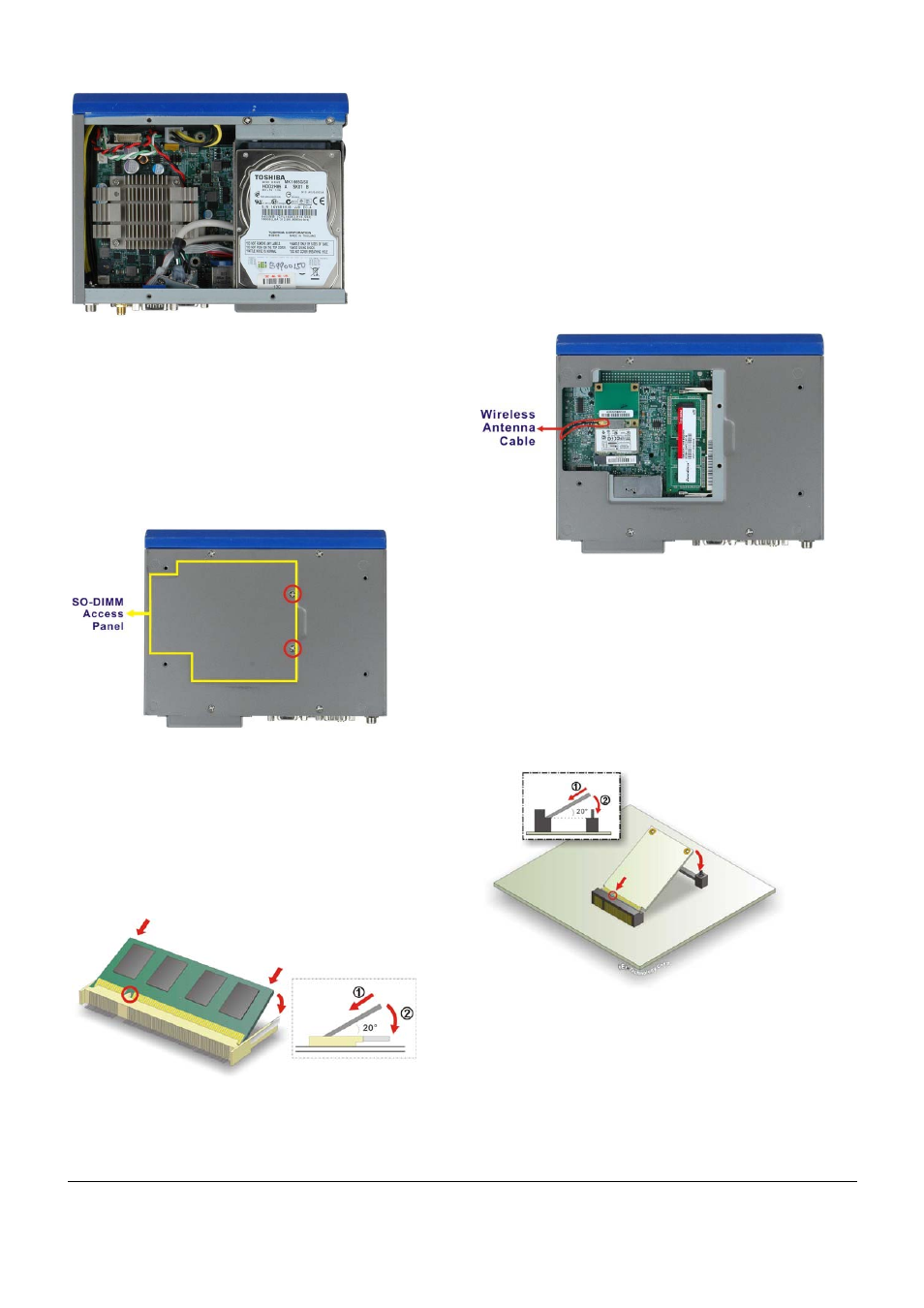
Figure 9: HDD Installation
Step 7:
Reinstall the top cover.
Step 0:
STEP 6: SO-DIMM INSTALLATION
To install the SO-DIMM, please follow the steps below.
Step 1:
Locate the SO-DIMM access panel on the bottom
of the chassis. Remove the two retention screws
and remove the panel.
Figure 10: SO-DIMM Access Panel Retention Screws
Step 2:
Locate the SO-DIMM socket on the motherboard.
Step 3:
Align the notch on the memory with the notch on
the memory socket. Push the memory in at a 20º
angle.
Step 4:
Gently push downwards and the arms clip into
place.
Figure 11: SO-DIMM Installation
Step 5:
Reinstall the SO-DIMM access panel.
Step 0:
STEP 7: WI-FI MODULE INSTALLATION
(OPTIONAL)
To install the optional Wi-Fi module, please follow the steps
below.
Step 1:
Locate the SO-DIMM access panel on the bottom
of the chassis. Remove the two retention screws
and remove the panel. See Figure 10.
Step 2:
Connect the Wi-Fi antenna cable from the
chassis to the Wi-Fi module.
Figure 12: Wi-Fi Antenna Cable Connection
Step 3:
Insert the Wi-Fi module into the PCIe Mini socket
at an angle. To do this, line up the notch on the
Wi-Fi module with the notch on the connector.
Slide the Wi-Fi module into the socket at an angle
of about 20º.
Step 4:
Push down until the card clips into place. Push
the other end of the card down until it clips into
place on the plastic connector.
Figure 13: Wi-Fi Module Installation
Step 5:
Reinstall the SO-DIMM access panel.
Step 0: