Step 1: unpack, Step 2: remove the top cover, Step 3: motherboard installation – IEI Integration ECN-581A-R10-D5251 User Manual
Page 3
ECN-581A-D5251/HM551 QIG IEI Technology Corp. Page 3
INSTALLATION STEPS
To install the ECN-581A chassis, the following installation steps
must be completed:
Step 1:
Unpack the chassis.
Step 2:
Remove the top cover.
Step 3:
Install the SBC (Single Board Computer).
Step 4:
Connect the cables.
Step 5:
Install the internal 2.5” HDD.
Step 6:
Reinstall the top cover.
Step 7:
Install a SO-DIMM.
Step 8:
Install the Wi-Fi module (optional)
Step 9:
Mount the chassis. (optional)
Step 0:
The installation steps outlined above are described in detail below.
Please refer to the relevant section.
STEP 1: UNPACK
The ECN-581A is shipped in a plastic bag that is placed inside a
cardboard box. The items are also shipped with the chassis. When
unpacking the chassis please:
Make sure all the items listed in the PACKING LIST
section are present.
Make sure the chassis has not been damaged in any
way.
STEP 2: REMOVE THE TOP COVER
The top cover is secured to the chassis with eight retention
screws. To remove the top cover, follow the steps below.
Step 1:
Remove the eight top cover retention screws on
the chassis, four on the top panel and four on the
right side panel.
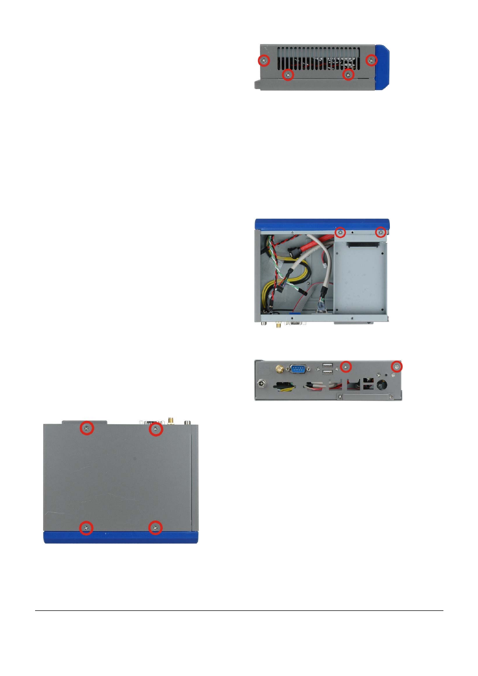
Figure 2: Top Cover Retention Screws (Top Panel)
Figure 3: Top Cover Retention Screws (Right Side Panel)
Step 2:
Slide the cover and then lift the cover up gently.
Step 0:
STEP 3: MOTHERBOARD
INSTALLATION
To install a NANO series motherboard, please follow the
instructions below:
Step 1:
Remove the HDD module bracket from the
chassis by removing the four retention screws on
the rear panel and inside the chassis.
Figure 4: HDD Bracket Retention Screws (Inside)
Figure 5: HDD Bracket Retention Screws (Rear Panel)
Step 2:
Place the motherboard inside the chassis. Make
sure the external peripheral interface connectors
fit into the predrilled holes on the rear of the
chassis.
Step 3:
Align the four retention screw holes on the
motherboard with the retention screw holes on
the bottom of the chassis.
Step 4:
Install the motherboard to the chassis with four
retention screws.
Step 0: