Getting started, Using the pulsar, Set-up – IPA Tools 9000 Pulsar Standard Kit User Manual
Page 8: Selecting an adapter, Selecting power mode
7
GETTING STARTED
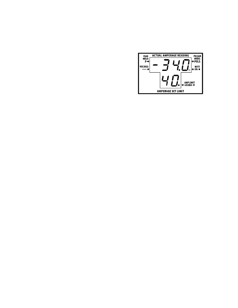
NOTE: The battery clips are different colors. When hooked in
reverse, the PULSAR™ displays a “-” (negative) line next to the
amperage reading. This indicates the flow of current only and does
not affect the operation of the tool.
1. SET-UP:
a.
Connect the 10’ ground cable to a
clean engine or battery
ground
connection.
NOTE: This ground is for Pulsars’
™
on-
board computer only, it does not carry
the main testing load.
b.
Select your Adapter and connect to
the desired circuit (See “Selecting
an Adapter”)
2. SELECTING AN ADAPTER:
a.
Battery Clip Adapters:
i. Parasitic Draw Testing: Use Battery Clip Adapter when
testing for Parasitic Draw. (See Section 14 on testing for
Parasitic Draw.)
ii. Bench Testing: Use the Battery Clip Adapter when Bench
Testing equipment or connecting in series with a wire. (See
Section 16 on Bench Testing.)
b.
Fuse Box Adapters: Select the “T” style adapter for Mini and
Standard blade type fuses and the large blade for maxi type
fuses. (See Section 15 on Troubleshooting Short Circuits.) The
large blade adapter can also be used to bypass common relays.
c.
Bench Test/Voltage Probe Adapter: Voltage Probe is used to
send current from the PULSAR
™
. While current is applied the
PULSAR
™
displays the amperage draw from the circuit providing
full overload protection. Do not exceed 20 AMPS. (See Section 16
on Bench Testing.)
USING THE PULSAR
™
3. SELECTING POWER MODE:
With the Adapters installed you must choose either Automatic or Manual
Testing Mode. Once the mode is selected the PULSAR
™
powers up (See
Section 4). Power is not applied to the circuit until an amperage limit is
set and engaged (See Section 5).
NOTE: The PULSAR
™
receives its power from the circuit. The
Adapter is plugged into and acts as a digitally controlled relay.
EXAMPLE OF UPPER
DISPLAY SHOWING
NEGATIVE CURRENT
FLOW (Fig. 3)