Critical points for a proper lpv gas installation – Gillette Generators SP-1500 User Manual
Page 22
PAGE 22
All new installations, plus any future repair or
troubleshooting procedures must include a natural
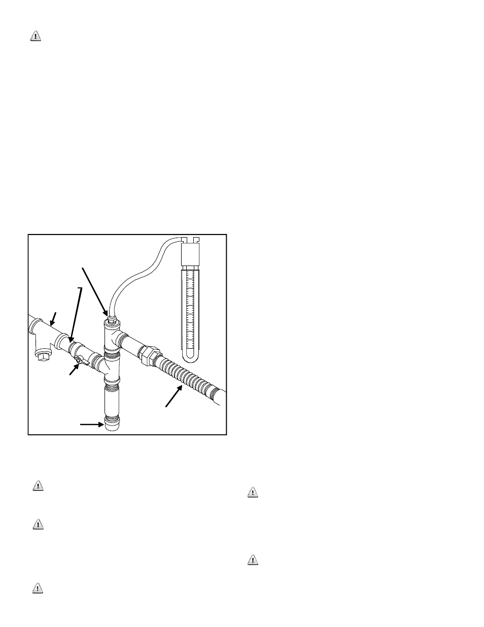
gas manometer test. This test should be conducted
after all other natural gas appliances have been
turned on. After all appliances are running, start
the generator. If manometer stays within 7 inches
water column with full load applied to a proper
running generator, it’s a good installation. (See
Figure 10)
If manometer reading falls below 7 inches water
column while generator engine is cranking, or
running, it may indicate the gas meter or primary
regulator is too small, or the fuel pressure from gas
supplier is inadequate. Any of these three problems
will cause a fault in proper generator operation.
If manometer reading stays within the 7 inches water
column, but generator engine still will not start, or it
runs erratic, it may indicate insufficient fuel volume
due to long fuel line runs or fuel pipe diameter is too
small. Check calculations of charts on page 20.
NOTE: After completion of all gas tests, remove
manometer and replace blank plug, using fresh pipe
sealant.
For additional precautions, a manual fuel shut-off
valve should also be installed inside the building, for
those locations with inside gas meters.
Climates that have snow and ice build-up, along
with sub-zero temperatures, should have gas fuel
piping protection against freezing. The generator
end of the hard piping installation should include a
sediment trap to drain any condensation, and a line
filter. (See Figure 10)
Best installations happen when electric utility
meter and gas meter are close together, as it results
in short runs for both electric wires and fuel lines.
When these two utilities are far apart, always choose
to locate gen-set close to the gas meter, as installation
costs are lower when increased electrical wire size
must be used for the long runs rather than increased
fuel pipe diameters.
CRITICAL POINTS FOR A PROPER LPV,
VAPOR WITHDRAWAL INSTALLATION
This generator system has been set up at the factory
for natural gas fuel, unless it has been specifically
ordered for vapor withdrawal liquid propane gas
(LPV). This installation/operation guide will explain
the factory LPV system. Additional information is
available upon request for field conversion from one
fuel to the other.
LPV fuel is typically at farms or remote areas where
there is no natural gas fuel.
LPV must be a vapor withdrawal system (the
generator will not work on liquid withdrawal
systems). Proper LPV is clean and free of moisture or
particulate matter. It consists of a propane HD5 grade
with minimum 2500 BTU’s per cubic foot energy
rating. A typical blend is 5% propylene and butane
plus a minimum 90% propane.
Required LPV vapor withdrawal fuel pressure is 11
-14 inches water column at (6-6½ ounces) 2500
BTU’s per cubic feet.
CAUTION: It is critically important to understand,
that as a specific fuel line pipe diameter is extended
in length, its ability to carry the volume of gas,
diminishes in direct proportion.
INSTALLER’S RESPONSIBILITY: Use chart (Table
A) on page 20 to learn fuel cubic feet/hour value of
generator to be installed. Use LPV fuel chart
(Table B) to learn minimum pipe size diameter
and maximum distance from LPV tank to insure
sufficient fuel volume from LPV tank to generator.
CRITICAL POINTS FOR A PROPER LPV
GAS INSTALLATION
Before LPV fuel line plans are made, call your
LPV supplier, give information on the amount of cubic
feet/hour and BTU’s/hour from tables on page 20, that
your generator will use, and ask about local codes
and regulations concerning LPV fuel connected to
generators.
Only LPV vapor withdrawal (not LPG liquid
withdrawal) will work on these generators. Make
sure the LPV tank has the correct fuel, and volume
capacity.
Manometer Port: Remove
Blank Plug And Insert
Manometer Plug
Dedicated Natural
Gas Fuel Line From
Natural Gas Meter
Line Filter
Manometer
Reading
Must Be
7” Water
Column
On/Off Valve
Sediment Trap
Flexible Stainless
Steel Gas Pipe
(without bends
or angles)
Gas Fuel To
Generator
Figure 10 NATURAL GAS LINE