Danger, Warning – Gillette Generators SP-1500 User Manual
Page 19
PAGE 19
1) “Standard” housing with standard interior sound
deadening foam and mounted residential grade
muffler.
2) “Super-Silent” housing with special interior foam
having damping material included.
3) “Super-Silent” housing also has a “Critical” grade
muffler included with a choice of “Hospital” grade
muffler as an additional upgrade.
4) “Super-Silent” housing also has an additional air
chute (much like the engine end air chute) for
increased generator end silencing.
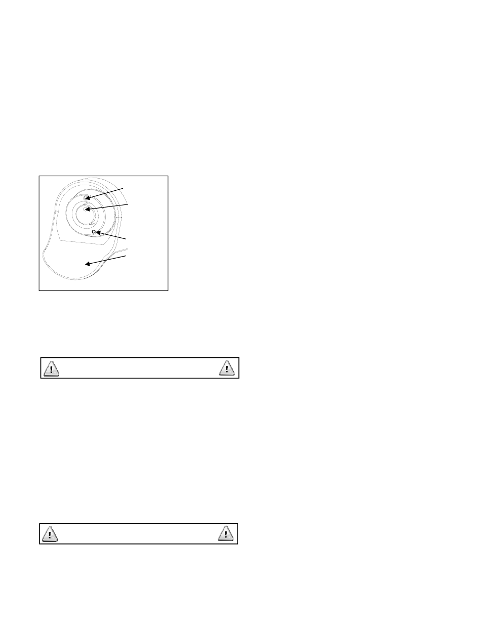
All generator
access doors are
locked, and are
opened with a
common key for
all locks. Notice
the door lock (in
t h e l o c k e d
position) has
matching dot
s y s t e m i n
alignment. Insert
the key into lock
and turn counterclockwise. Remove the key and
note, the dots are now out of alignment. Re-insert the
key, turn clockwise until dots align, and it’s in the
locked position. All doors are hinged, and once
unlocked, will swing open. All keys are universal,
used on all housing sizes.
All doors have grounding wire, connecting and
grounding door to housing frame. DO NOT
REMOVE these grounding wires. If it becomes
necessary to remove and replace door, be sure to
replace grounding wire and to reuse self grounding
star washers, to prevent accidental electrical shock,
if live circuit wires were to touch housing parts.
EXHAUST SYSTEM
The engine end of housed gen-set will have hot
exhaust air discharge from engine muffler, mounted
within housing for complete generator hot air
discharge.
Even though the muffler is safely concealed within
hot air engine exhaust chute, the muffler exhaust
pipe and its accompanying rain cap, extending
straight up from roof, will cause severe burn to the
DANGER
WARNING
touch. This “Hot Pipe Burn” warning remains in
effect for 60 minutes after shut-down of generator set.
CORROSION TO GENERATOR AND
HOUSING
Depending on the area of generator installation, will
depend on the amount of attention given to gen-set
cleanliness. Heavy concentration of salt water
exposure (USA Coastal Regions, and Tropics), will
require frequent washings and a final waxing of
generator housing, much like an automobile’s
special care in these areas. Salt corrosion may enter
the generator interior, which may have to be
removed by special detergents. Every 3 months,
spray the engine governor linkage, springs, and
other engine control moving parts with a light spray
coverage of WD-40 to help prevent or prolong
corrosion destruction.
In severe Coastal or Tropical conditions, it is advised
to use aluminum housings, as opposed to steel
housings.
DRY FUEL GAS PIPE SIZING
INFORMATION
Fuel line diameter depends on the amount of fuel
needed to run an engine-generator at full load and at
the distance the fuel must be moved. Refer to the fuel
specification sheet on page 20.
INSTRUCTIONS IN FINDING CORRECT PIPE
SIZES: Use engine HP or KW size of the gen-set to
find fuel consumption on either LPV or Natural Gas.
Then use this fuel consumption amount to match up
with the length of fuel pipe run, to determine pipe
diameter.
EXAMPLE 1: A 30 KW gen-set having 48 HP engine
with Natural Gas fuel is to be located 95 feet from
source of fuel. Locate fuel consumption in Table A for
42 HP = 539 cu. ft. for Natural Gas fuel. Locate closest
fuel consumption in Table C, to 539 cu. ft. under
Column 91-100 ft. run = 605 cu. ft. Locate the pipe
diameter for this amount of fuel, at left side of Table C
= 1½” Dia.
EXAMPLE 2: A 100 KW gen-set having a 162 HP
engine with LPV fuel is installed 125 ft. from LPV tank.
Locate fuel consumption in Table A for 100 KW, 162
HP = 595 cu. ft. In Table B, locate the closest cu. ft. to
595 under 116-125 pipe length, column = 679 cu. ft.
Locate pipe diameter for this amount of fuel at left
side of Table B = 1¾ diameter.
EXAMPLE 3: A 20 KW gen-set having a 42 HP
engine with Natural Gas fuel is installed 15 Ft. from
source of fuel. Locate fuel consumption in Table A for
20 KW, 42 HP = 387 Cu. Ft. for Natural Gas fuel. In
Table C, locate the closest fuel consumption to 387
ACCESS TO HOUSING INTERIOR
Stationary Dot
Dot-aligned,
Locked
Position
Un-Locked
Position
Raised
Finger
Hold
FIGURE 9