Hf series, General pump – General Pump HF Owner Manual User Manual
Page 7
GENERAL PUMP
A member of the Interpump Group
HF SERIES
Page 7
9. PUMP INSTALLATION
9.1 Positioning
The pump must be installed on a rigid and perfectly flat
and horizontal base by means of the proper four M16 x 1.5
threaded feet. The base should be rigid enough to avoid
any misalignment or flexing on the pump/transmission cou-
pling axis due to the torque involved during operation.
The unit should not be rigidly fixed on the floor
but be installed upon vibration dampeners. For
special applications contact our technical department.
An eye-bolt is provided on top of the crankcase for easy
handling of the pump (see picture below).
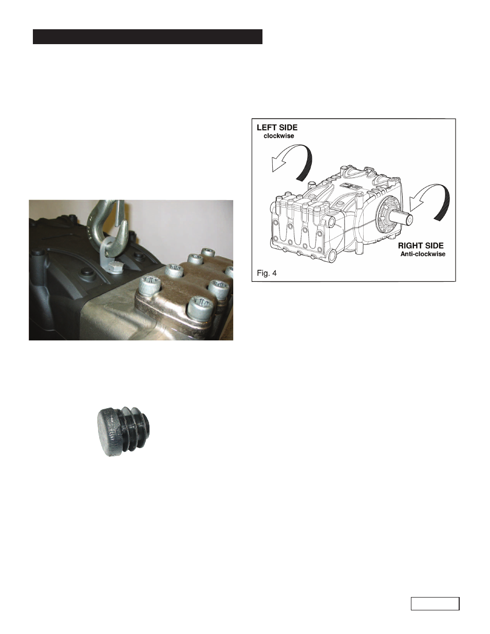
9.2 Direction of rotation
An arrow situated on the crankcase near the shaft
indicates the correct direction of rotation. Fig. 4 shows
the direction of rotation looking at the pump from
the fluid end side.
9.3 Water connections
In order to isolate the high pressure equipment from the
pump vibrations it is suggested, where applicable, to use
flexible hoses for both suction and delivery lines at least
for the first length. The flexible suction hose must be
rigid enough to prevent it from collapsing during the
suction stroke, when a partial vacuum may occur.
9.4 Suction line
The pump life is considerable influenced by the effective-
ness of the suction line which must have the following
characteristics:
1. The internal diameter of the suction line should be at
least 30 mm (see the diagram on point 9.7) in any
point, possibly larger depending on the drop in
pressure due to the length and shape of the line.
2. It should be as straight as possible minimizing
changes in size and direction and positioned in such
a way to allow air pockets and bubbles to escape.
3. It should be perfectly airtight.
4. It should be completely free from 90o elbows, diameter
reductions, counter slopes, “T” connections and and
should not be connected with other pipelines.
5. It must be positioned in such a way to prevent the pipe
emptying after the pump stops.
6. Do not use high pressure hydraulic fittings like 90
o
elbows, high pressure adaptors, high pressure 3 or 4
way nipples, and so on.
7. Do not install any kind of detergent infector along the
suction line.
8. Do not install standing valves, check valves or other
The eye bolt can be replaced with a plastic cap (see
below), in order to protect the thread in the crankcase.
The plastic cap is provided with the pump.
The oil plug must absolutely be replaced by the oil
stick and the oil level checked. Make sure that you can
easily reach the oil stick even after the unit has been
assembled.
Never use rigid coupling on the shaft.
The following transmission types are suggested:
-
Hydraulic by means of a flange
-
Pulleys
-
Cardan joint (within the max working angles indicated
by the manufacturer).