Installation, Temperature control, Water supply – Fulton Electric (FB-W) Hot Water Boiler User Manual
Page 11: Step controllers, Water quality, Water specifi cation
Questions? Call (315) 298-5121, or visit us online at www.fulton.com
SECTION 2
FBW-IOM-2014-0311
INSTALLATION
2-5
Drain Valve
PID Type Temperature Controller
Boilers 100kW and larger: staged element sequencer for
modulation of output
Temperature Control
Temperature control is achieved via an operating and high
limit temperature controller. The high limit temperature
controller is a temperature switch that is set to shut the boiler
off if the water temperature exceeds the set point. For ASME
Section IV hot water boiler, the high limit must be below 250
F.
The operating controller is a temperature sensor and PID
Type controller that converts a temperature measurement
into a 4-20 ma signal. The signal, which is proportional to the
temperature of the water in the boiler, is used to energize/de-
energize the contactors or step controller. The step controller
(power modulation) will energize/de-energize each element
based on a preset sequence to maintain the outlet water at a
preset temperature.
Step Controllers
At start up stage number one is fi rst “on” with additional
stages added as demanded. When set point is reached, the
fi rst “on” stage is removed followed by the next stage “on”.
Where control is a fraction of the total load, a sequence of on-
steps will advance through the total number of stages, trailed
by a sequence of “off ” steps. In this way all contactors and
heaters tend to operate equally.
A back up operating temperature switch is supplied on each
boiler and will act to energize/de-energize all elements
simultaneous based on boiler water outlet temperature.
Water Supply
Water Quality
The quality of the water used in the boiler will aff ect the
life of the elements and pressure vessel and it is strongly
recommended that a competent water treatment concern
be consulted prior to the operation of the boiler. Boiler
internals damaged due to adverse water conditions cannot
be replaced under warranty.
Water Specifi cation
All water supplies contain some amount of solids, dissolved
gases and dissolved minerals. These materials may promote
corrosion, deposition and/or fouling of equipment. To prevent
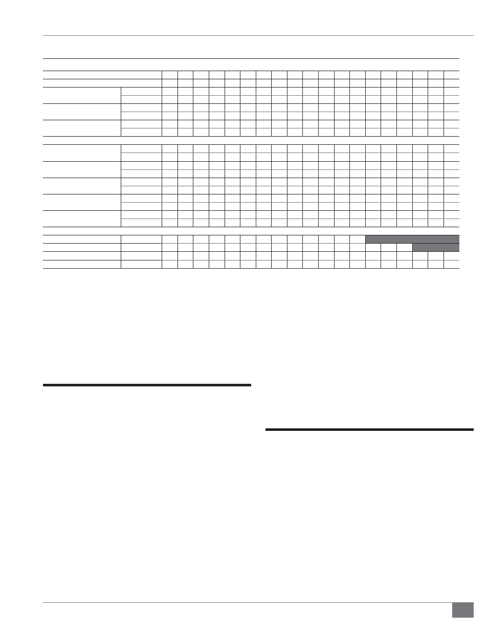
TABLE 1B - SPECIFICATIONS
Model FB-W
012
015
018 024 030 036 050 070 105 140 175
210 280 350 420 490 560 630 700
Number of Elements
1
1
1
2
2
2
2
2
3
4
5
6
4
5
6
7
8
9
10
Output
1000 BTU/HR
41
51
62
82
103
124
172
241
362
483
603
724
966 1207 1449 1690 1932 2173 2415
1000 KCAL/HR
10
13
16
21
26
31
43
61
91
122
152
182
243
304
365
426
487
548
609
Approx. Shipping Weight
LB 420
420
420
450
450
450
580
580
950 1088 1225 1225 1380 1615 1850 2039 2150 2320 2660
KG 191
191
191
204
204
204
263
263
431
494
556
556
626
733
839
925
975 1052 1207
Water Capacity
GALLONS
13
13
13
13
13
13
21
21
51
51
68
68
132
133
133
169
169
234
234
LITERS
49
49
49
49
49
49
79
79
193
193
257
257
500
503
503
640
640
886
886
Heater Connection Sizes
Hot Water Outlet
IN 1.25 1.25 1.25 1.25 1.25 1.25
2
2
2
2
2
2
2
2
2.5
3
3
3
3
MM
32
32
32
32
32
32
51
51
51
51
51
51
51
51
64
76
76
76
76
Hot Water Inlet
IN 1.25 1.25 1.25 1.25 1.25 1.25
2
2
2
2
2
2
2
2
2.5
3
3
3
3
MM
32
32
32
32
32
32
51
51
51
51
51
51
51
51
64
76
76
76
76
Drain Outlet
IN
1
1
1
1
1
1
1
1
1
1
1.25 1.25 1.25 1.25
1.5
1.5
1.5
1.5
1.5
MM
25
25
25
25
25
25
25
25
25
25
32
32
32
32
38
38
38
38
38
Safety Valve Inlet (160 PSIG)
IN 0.75 0.75 0.75 0.75 0.75 0.75 0.75 0.75 0.75 0.75 0.75 0.75 0.75 0.75 0.75 0.75 0.75 0.75 0.75
MM
19
19
19
19
19
19
19
19
19
19
19
19
19
19
19
19
19
19
19
Safety Valve Outlet (160 PSIG)
IN
1
1
1
1
1
1
1
1
1
1
1
1
1
1
1
1
1
1
1
MM
25
25
25
25
25
25
25
25
25
25
25
25
25
25
25
25
25
25
25
Electrical Power Requirements (Amps)
208V 3 Phase
34
42
50
67
84
100
139
195
292
389
486
583
778
Consult Factory
230V 3 Phase
31
38
46
61
76
91
126
176
264
352
440
528
703
879 1055 1231
Consult Factory
460V 3 Phase
16
19
23
31
38
46
63
88
132
176
220
264
352
440
528
616
703
791
879
575V 3 Phase
13
16
19
25
31
37
51
71
106
141
176
211
282
352
422
493
563
633
703
Specifi cations are approximate.
Fulton reserves the right to change dimensions and/or specifi cations without notice. Voltage applied higher than the above ratings will
result in higher amp draws. 160 PSIG design boilers operate up to 130 psi, 230 F.