Fluid Components International MT91 Manual Installation User Manual
Page 8
FLUID COMPONENTS INTL
CHAPTER 2 - INSTALLATION
Model MT91 Multipoint Flowmeter
2 - 8
Doc. No. 003185 Rev. B
Note:
Do not wire to HBS and HBX terminals.
3.
Plug back in the connectors to the appropriate sockets, matching sensing point number to each socket number.
For example, connect sensing point 1 to socket J1. See Figure 2-3.
4.
After connecting all sensing points, plug the display ribbon cable back into J18 and secure panels of enclosure.
Customer Connections
Analog Output Board - Assy #015231 (see Figure 2-3 for location)
Note:
If a different jumper position is selected other than the factory calibrated position, a complete re-calibration
of the analog output board will be necessary. See Chapter 3 for how to calibrate the analog output board.
Jumper J2
This jumper provides three output options for channel 1. Select one and place the jumper in the corresponding
position. See Figure 2-2 for jumper location.
4 to 20 milliamperes
0 to 10 volts
0 to 5 volts
Jumper J3
This jumper provides three output options for channel 2. Select one and place the jumper in the corresponding
position. See Figure 2-2 for jumper location.
4 to 20 milliamperes
0 to 10 volts
0 to 5 volts
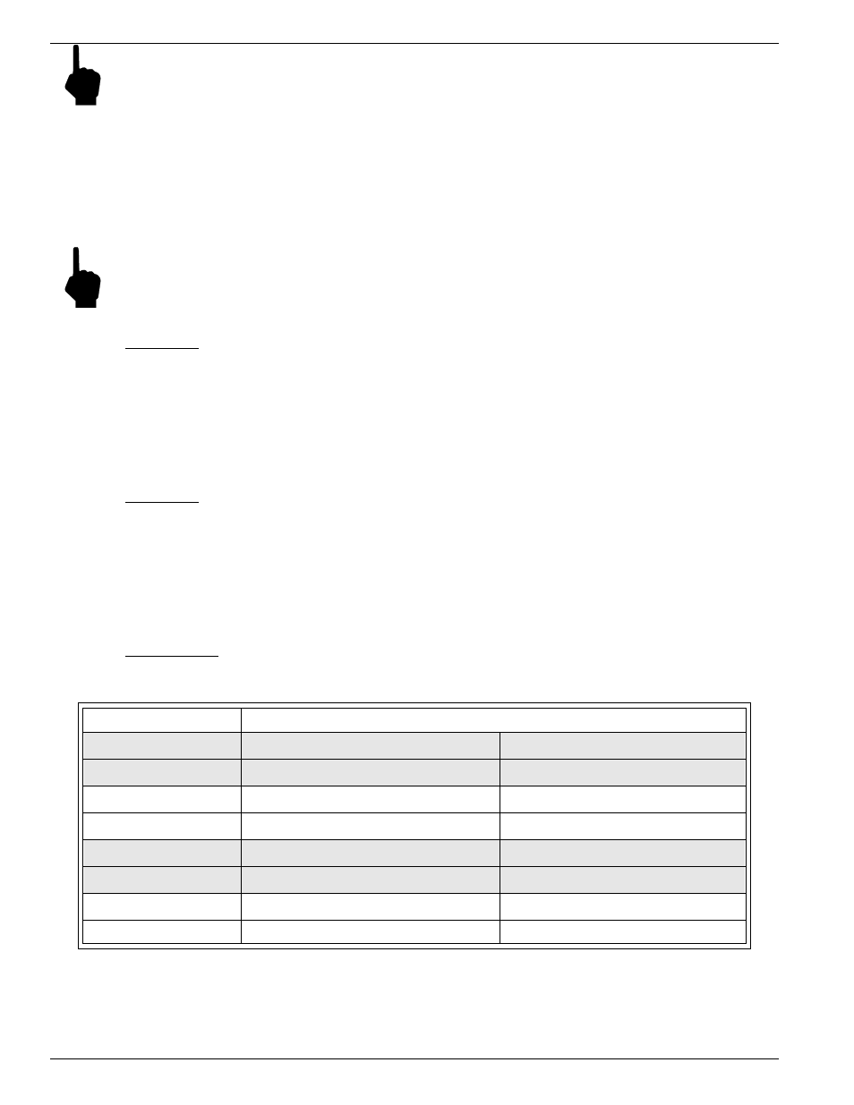
Connector J4
This connector interfaces with customer instrumentation. Refer to Table 2-2 for signal information.
Table 2-2. Connector J4 Signal Information
Signal (Power Isolated)
Description
Vout2-
Channel 2 voltage output return.
Connected to system signal ground.
Vout2+
Channel 2 voltage output signal.
0 to 5 Vdc or 0 to 10 Vdc
MA2-
Channel 2 current output return.
Connected to system signal ground
MA2+
Channel 2 current output signal.
0 to 22 mAdc
Vout1-
Channel 1 voltage output return.
Connected to system signal ground.
Vout1+
Channel 1 voltage output signal.
0 to 5 Vdc or 0 to 10 Vdc
MA1-
Channel 1 current output return.
Connected to system signal ground.
MA1+
Channel 1 current output signal.
0 to 22 mAdc