Fluid Components International MT91 Manual Installation User Manual
Page 10
FLUID COMPONENTS INTL
CHAPTER 2 - INSTALLATION
Model MT91 Multipoint Flowmeter
2 - 10
Doc. No. 003185 Rev. B
Serial Communication Ports - Backplane Board Assy # 015206 (see Figure 2-3 for
location)
Connector J17 - EIA-232
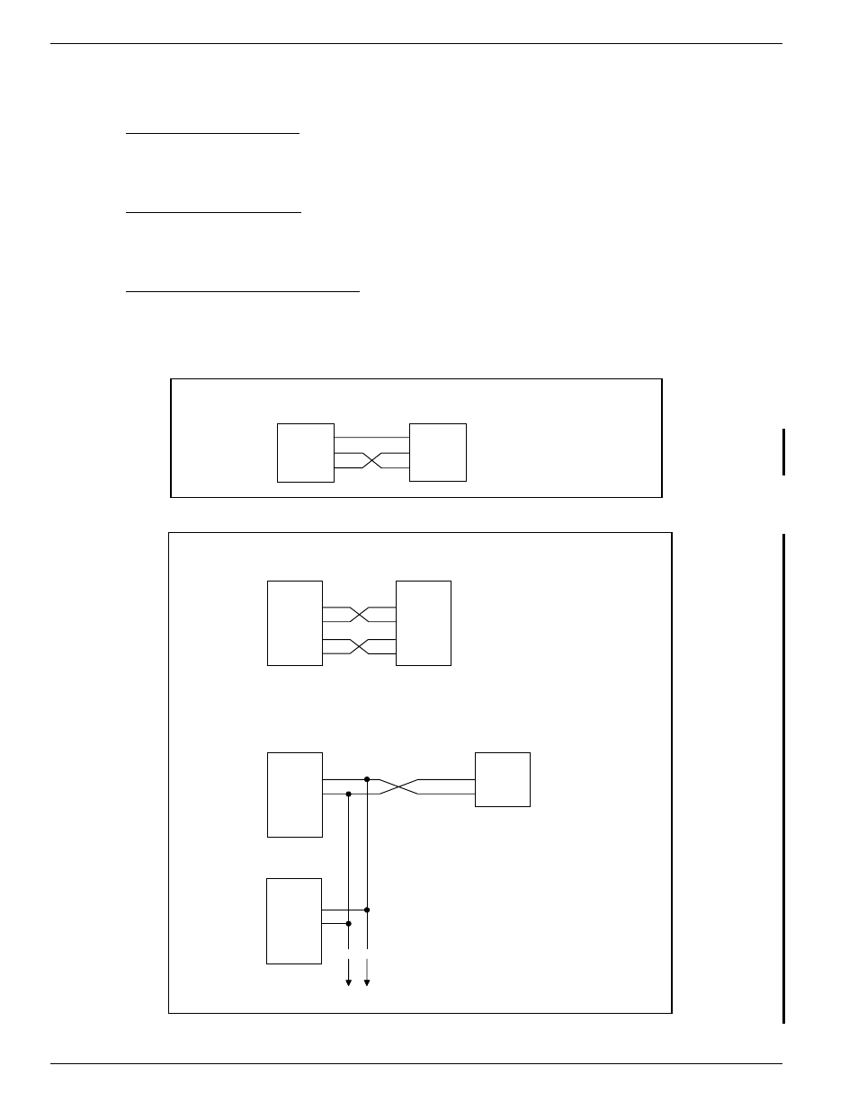
This connector provides serial communications for compatible equipment. Refer to Figure 2-4 for wiring
configuration.
Connector J23 - 4-20 mA
This connector provides analog communication for compatible equipment. Refer to Figure 2-2 for wiring
information.
Connector J24 - EIA-422/EIA-485
This connector provides serial communication for compatible equipment for a EIA-422 port or EIA-485 port. To
use the EIA-422 connection, wire according to Figure 2-2 and 2-5. To use the EIA-485 connection, wire only the
GND, RX+, and RX- according to Figure 2-2 and 2-5. Multiple instruments can interface with the host system with
the EIA-485 connectors.
5
3
2
E I A - 2 3 2
C o n n e c t o r
G N D
T X
R X
H o s t
G r o u n d
T r a n s m i t D a t a
R e c e i v e D a t a
G N D
T X
R X
C00287-1
Figure 2-4. Wiring Diagram for Serial Connector EIA-232
5
4
3
2
1
E I A - 4 2 2
C o n n e c t o r
G N D
TX -
T X +
RX -
R X +
H o s t
G r o u n d
Transmit Data Return
Transmit Data
Receive Data Return
Receive Data
G N D
R X +
RX -
T X +
TX -
5
4
3
2
1
E I A - 4 8 5
C o n n e c t o r
G N D
TX -
T X +
H o s t
G r o u n d
Transmit Data Return -
Transmit Data +
G N D
R X +
RX -
T X +
TX -
5
4
3
2
1
E I A - 4 8 5
C o n n e c t o r
G N D
R X +
RX -
T X +
TX -
Instrument #2
F l o w
Transmitter #1
Figure 2-5. Wiring Diagram for Serial Connectors EIA-422 & EIA-485