Fluid Components International MT91 Manual Installation User Manual
Page 4
FLUID COMPONENTS INTL
CHAPTER 2 - INSTALLATION
Model MT91 Multipoint Flowmeter
2 - 4
Doc. No. 003185 Rev. B
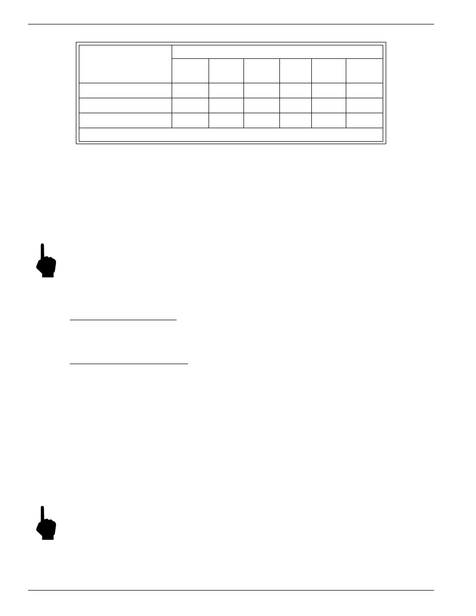
Table 2-1. Interconnecting Cable Size (AWG)
Connection
Maximum Distance for AWG
10 ft.
(3m)
50 ft.
(15m)
100 ft.
(31m)
250 ft.
(76m)
500 ft.
152m)
1000 ft.
(305m)
AC Power
22
22
22
20
18
16
Relay (2A)
28
22
20
16
12
10
Flow Element Wires*
24
24
24
22
22
18
*Requires a shielded cable which is connected to the Flow Transmitter
Remote Hardware
Figures A-3 and A-4 show the remote enclosures along with physical dimensions to properly mount the flow
transmitter. Select a location for the flow transmitter within 1000 feet of the flow element. This location should be
easily accessible with enough room to open the enclosure cabinet door or remove a panel at any time. Secure the
flow transmitter solidly to a vertical surface capable of providing support. Use nuts and bolts to secure the flow
transmitter.
Power Connection Information
Note:
The installation of an AC line switch between the AC power source and the flowmeter is recommended.
This facilitates easy power disconnection and is an added safety feature.
The flow element power supply is not field selectable. Connect 85-265 Vac operating power and a power ground to
the flow transmitter. Follow the appropriate procedure below to connect power.
NEMA 4 Remote Enclosure
Install the customer supplied conduit and/or cable through the 1 inch female NPT ports. Remove the terminal block
shield located at the top right hand corner on TB1 and wire according to Figure 2-2.
Rackmount Remote Enclosure
Install the customer supplied conduit or cable though the back side of the enclosure. Remove the terminal block
shield located on the left wall (looking from the rear) on TB1 and wire according to Figure 2-2.
Sensing Point Connections
There are up to 16 different sensing points per flow transmitter. Sensing point 1, on the flow element, is the point
closest to the local enclosure. Sensing point 2 is the next down, etc.
In the local enclosure, sensing points are identified on the terminal board. For example, TB1-HD1 connects to
sensing point 1. In the remote enclosure, sensing points are identified by the connector number. For example, J1
corresponds to sensing point 1.
1.
Run eight-conductor-shielded cable from the local enclosure to the remote enclosure for each sensing point. Use
Table 2-1 to determine which wire gauge to use.
2.
In the local enclosure is an 8-pin connector for each sensing point, wire each cable to a connector per Figure 2-2.
Note:
Before inserting the cable wires into the terminal strip connector, turn the screw counterclockwise 7 turns.
If this is not done, it is possible to insert the wire between the top half of the clamp and the frame instead of
between the two clamp segments.
3.
Tag the cables to clarify which cable connects to which sensing point. Follow the appropriate procedure below
to connect sensing points.