I-View CP-2160RD Deluxe Real Time Recording DVR Card User Manual
Page 2
2
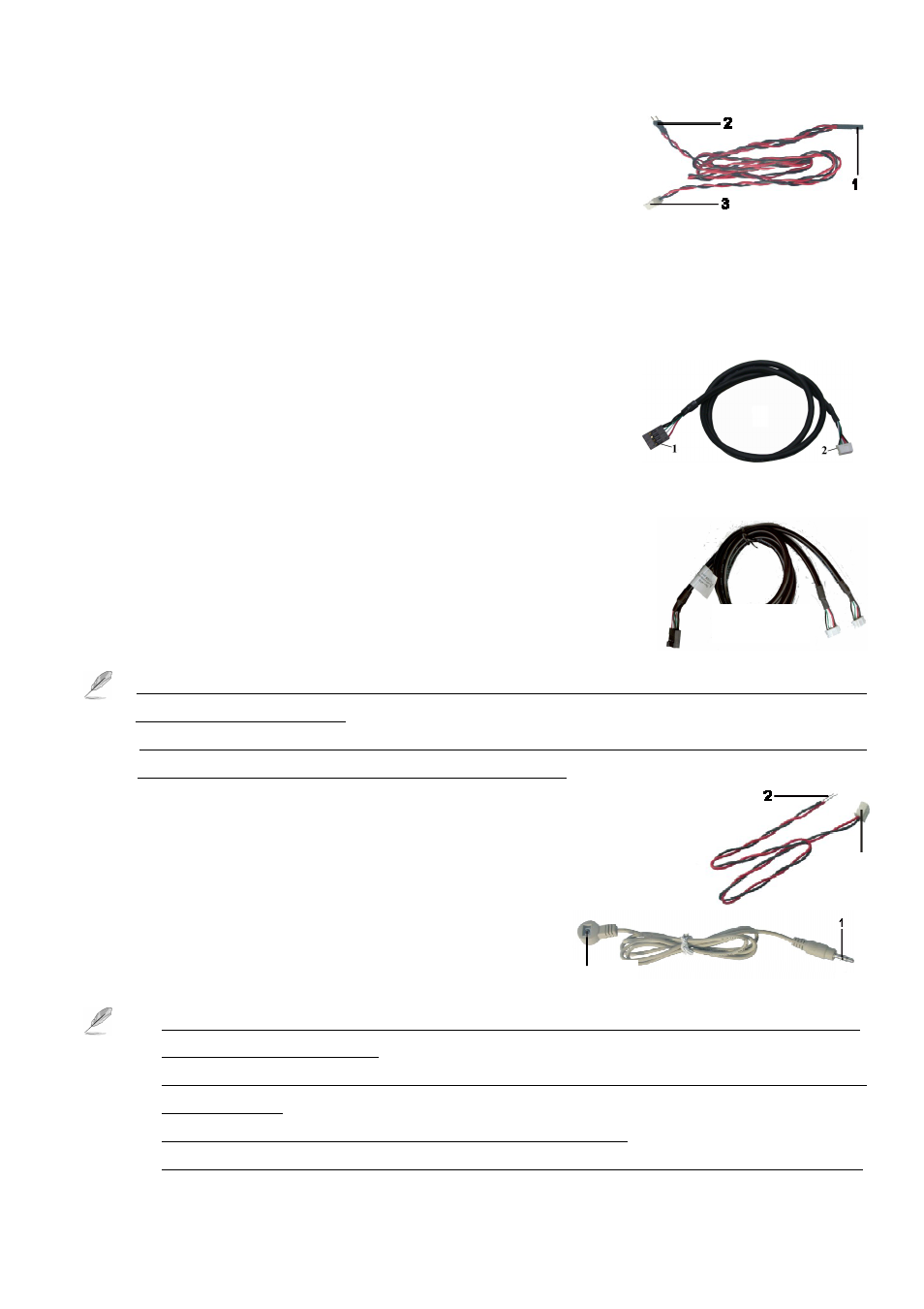
(A) System Failure Connections cable as shown in “Fig 2”:
The DVR system will reboot and restore to the original status
automatically when system crush occurs. Please follow the steps below to
connect these cables properly:
Connect the “3” connector of the “Fig 2” cable to the RST socket of DVR board.
Connect the “1” connector of the “Fig 2” cable to the Motherboard reset pin.
Connect the “2” connector of the “Fig 2” cable to the PC’s reset switch properly to complete.
(B) USB linking cable as shown in “Fig 3”:
Please follow the below steps to connect the USB cable to the CP-2160RD
Deluxe DVR Board and motherboard properly.
Plug the number “2 “connector of the “Fig 3” cable into the J_USB
socket of each CP-2160RD Deluxe Board
Connect the number “1 “connector of the “Fig 3” cable to the USB
port of the motherboard.
The pins assignment of the “Fig 3” cable is:
Red: Vcc 5V White: Data- Green: Data+ Black: Ground
There is a two ports internal USB cables (refer to Fig 3.1) on the package
of CP-2160RD Deluxe DVR Board. You can use Fig 3.1 USB cable to
connect 2 pcs DVR board and the internal USB port of PC when the
Motherboard does not have enough internal USB port.
1. The USB cable must be connected between DVR board and Motherboard; otherwise you cannot run the
Witness Pro program properly.
2. You can request the external USB cable from your supply to connect the USB port of PC when the
Motherboard does not have enough internal USB port. (Option
(C) Panic Button as shown in “Fig 4”:
Connect the number “1” connector to the J 8 (EM_B) of the CP-2160RD
Deluxe 0 DVR Board.
And then connect the number “2” connector to the panic button.
(D) Sensor cable as shown in “Fig 5”
To install the sensor, simply plug the end of the sensor device
(“1” connector of the “Fig 5 ”) into the Sensor connector
of CP-2160RD Deluxe 0 DVR Board.
1. Please shut down the power of PC when you plug in the sensor cable into the DVR board, otherwise
it will cause the sensor damage.
2. Make sure that the sensor itself is not covered and is facing the place from where you will be using the
remote controller.
3. Make sure that the sensor itself plug into the phone jack completely.
4. The system allows to extent sensor cable (Fig 6) for control the TV out from far away site via Remote
(Fig 2)
(Fig 3)
(Fig 4)
(Fig 5)
1
Sensor
(Fig 3-1)