3 block diagram – Rainbow Electronics ATA6286 User Manual
Page 8
8
4958AS–AUTO–09/06
ATA6285/ATA6286 [Preliminary]
3.3
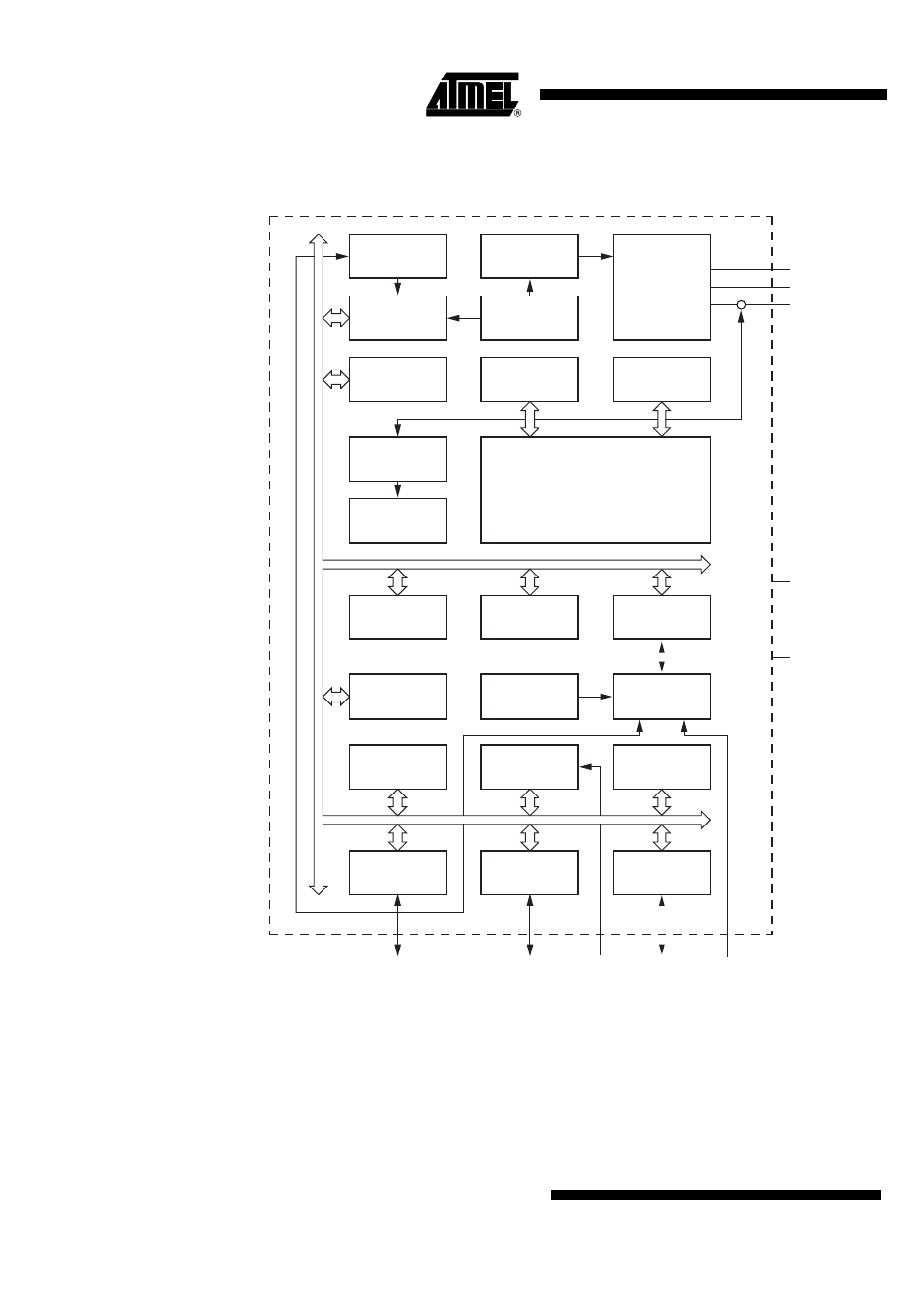
Block Diagram
Figure 3-1.
Microcontroller Block Diagram
AVR Core
GND
RESET
VCC
Power
Supervision
POR/ BOD/
TSD and
RESET
Clock
management
and monitoring
Watchdog
oscillator
Watchdog
timer 0
Flash
SRAM
Temperature
sensor
MUX and
sensor input
Voltage
monitor
12 bit T1
16 bit T/ C3
LF receiver
SPI
PORT D (x)
PORT B (x)
PORT C (x)
16 bit T/ C2
Sensor value
processing
debugWIRE
EEPROM
Program
logic
Oscillator
circuit
AVCC
AGND
See also other documents in the category Rainbow Electronics Software:
- MAX14514 (14 pages)
- MAX16825 (15 pages)
- MAX16800 (9 pages)
- MAX6931 (14 pages)
- MAX6920 (10 pages)
- MAX6959 (19 pages)
- MAX15025 (16 pages)
- EVK2 (2 pages)
- MAX13256 (17 pages)
- MAX6964 (23 pages)
- MAX6948B (28 pages)
- MAX17117 (22 pages)
- MAX6934 (16 pages)
- MAX5048 (9 pages)
- MAX15054 (9 pages)
- AT6010LV (28 pages)
- AT83C24NDS (42 pages)
- AT83C21GC (6 pages)
- AT42QT1012 (6 pages)
- ATF16LV8C (11 pages)
- ATA6823 (28 pages)
- 71M6542G (165 pages)
- ATV2500BQL (21 pages)
- ATV750BL (19 pages)
- ATA6839 (17 pages)
- BA6229 (3 pages)
- ATF16V8C (18 pages)
- ATMOS™ 1M60 (26 pages)
- ATF1504ASVL (29 pages)
- BA6955N (9 pages)
- ATF1500ABV (15 pages)
- BA6219BFP-Y (7 pages)
- AT77C102B (19 pages)
- AT90SCR050 (4 pages)
- BA6208F (2 pages)
- ATA6625 (22 pages)
- ATA6664 (20 pages)
- ATF1516ASL (13 pages)
- ATF20V8BQL (18 pages)
- ATA6827 (15 pages)
- AT83C26 (77 pages)
- AT77C104B (36 pages)
- ATA6830 (23 pages)
- AT42QT1040 (18 pages)
- ATA6824 (22 pages)