Rainbow Electronics ATA6286 User Manual
Page 15
15
4958AS–AUTO–09/06
ATA6285/ATA6286 [Preliminary]
4.5.3
Accuracy of Frequency Deviation
The accuracy of the frequency deviation using the XTAL pulling method is about ±20% if the fol-
lowing tolerances are considered. One important aspect is that the values of C
0
and C
M
of
typical crystals are strongly correlated which reduces the tolerance of the frequency deviation.
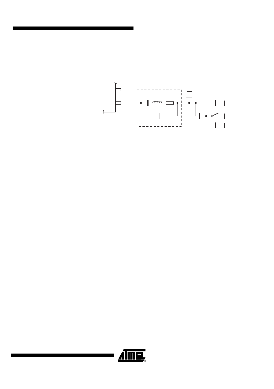
Figure 4-6.
Tolerances of Frequency Modulation
Using a crystal with a motional capacitance of C
M
= 4.37 fF ±15%, a nominal load capacitance
of CL
NOM
= 18 pF and a parallel capacitance of C
0
= 1.30 pF correlated with C
M
results in
C
0
= 297
×
C
M
(the correlation has a tolerance of 10%, so C
0
= 267 to 326
×
C
M
). If using the
internal FSK switch with C
Switch
= 0.9 pF ±20% and estimated parasitics of C
Stray
= 0.7 pF ±10%,
the resulting C
4
and C
5
values are C
4
= 10 pF ±1% and C
5
= 15 pF ±1% for a nominal frequency
deviation of ±19.3 kHz with worst case tolerances of ±15.8 kHz to ±23.2 kHz.
4.5.4
Accuracy of the Center Frequency
The imaginary part of the impedance in large signal steady state oscillation IM
XTO
, seen into the
pin 7 (XTO1), causes some additional frequency tolerances, due to pulling of the XTO oscillation
frequency. These tolerances have to be added to the tolerances of the crystal itself (adjustment
tolerance, temperature stability and ageing) and the influence to the center frequency due to tol-
erances of C
4
, C
5
, C
Switch
and C
Stray
. The nominal value of IM
XTO
= 110
Ω
, C
Switch
and C
Stray
should be absorbed into the C
4
and C
5
values by using a crystal with known frequency and
choosing C
4
and C
5
, so that the XTO center frequency equals the crystal frequency, and the fre-
quency deviation is as expected. Then, from the nominal value, the IM
XTO
has ±90
Ω
tolerances,
using the pulling formula P = –IM
XTO
×
C
M
×
Pi
×
f
XTO
with f
XTO
= 13.56 MHz and C
M
= 4.4 fF an
additional frequency tolerance of P = ±16.86 ppm results. If using crystals with other C
M
the
additional frequency tolerance can be calculated in the same way. For example, a lower
C
M
= 3.1 fF will reduce the frequency tolerance to 11.87 ppm, where a higher C
M
= 5.5 fF
increases the tolerance to 21.07 ppm.
4.5.5
CLK Output
An output CLK signal of 1.64 MHz (ATA6285 operating at 315 MHz) and 1.69 MHz (ATA6286
operating at 433.92 MHz) is provided for a connected microcontroller. The delivered signal is
CMOS-compatible with a High and Low time of >125 ns if the load capacitance is lower than
20 pF. The CLK output is Low in power-down mode due to an internal pull-down resistor. After
enabling the PLL and XTO the signal stays Low until the amplitude of the crystal oscillator has
reached 35% to 80% of its amplitude. Then, the CLK output is activated synchronously with its
output signal so that the first period of the CLK output signal is a full period.
R
S
L
M
C
4
C
M
V
S
XTAL
C
0
C
5
C
Switch
Crystal equivalent circuit
C
Stray