Port management > link aggregation, Chapter, Configuration using the web-based utility – Linksys SLM224G4S User Manual
Page 26
Chapter
Configuration Using the Web-based Utility
20
24/48-Port 10/100 + 4-Port Gigabit Resilient Clustering Smart Switch with 2 Combo SFPs
10 Half
The port advertises 10 Mbps half-duplex
operation.
10 Full
The port advertises 10 Mbps full-duplex
operation.
100 Half
The port advertises 100 Mbps half-duplex
operation.
100 Full
The port advertises 100 Mbps full-duplex
operation.
1000 Full
(Gigabit ports only) The port advertises
1000 Mbps full-duplex operation.
Current
Advertisement
(Read-only)
The
speed
and duplex mode settings that the port is currently
advertising.
Neighbor Advertisement
(Read-only) The speed and
duplex mode settings that the neighbor port (the port to
which the selected port is connected) is advertising. If the
port has no neighbor port, this field displays “Unknown.”
Back Pressure
Select Enable or Disable (default) to
enable or disable Back Pressure mode on the port.
Current Back Pressure
(Read-only) The current Back
Pressure mode on the port.
Flow Control
Select Enable or Disable to manually
enable or disable flow control, or select Auto-Negotiation
for automatic selection of flow control on the port.
Current Flow Control
(Read-only) The current flow
control setting.
MDI/MDIX
Select the port’s MDI/MDIX type, either MDI,
or MDIX. The MDI setting is used if the port is connected
to an end station. The MDIX setting is used if the port is
connected to a hub or another switch.
Current MDI/MDIX
(Read-only) The port’s current MDI/
MDIX type.
LAG
(Read-only) The LAG to which this port belongs, if
the port is a LAG member.
Click Save to save the settings and leave the screen open.
Click Save & Close to save the settings and close the
screen. Click Close to close the screen without saving the
settings.
•
•
•
•
•
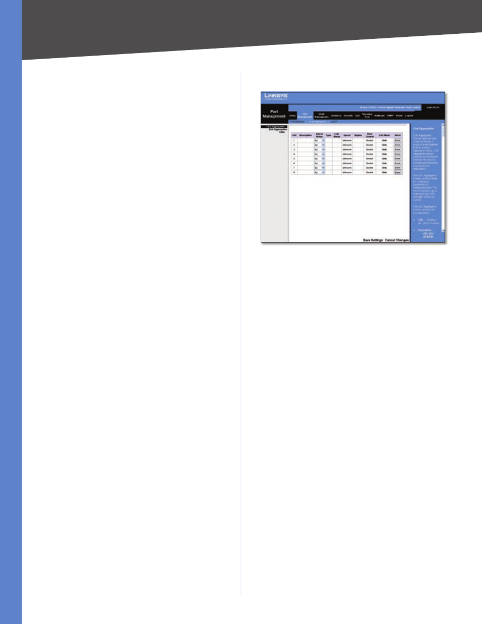
Port Management > Link Aggregation
Port Management > Link Aggregation
You can create multiple links between devices that work
as one virtual, aggregate link. This is known as a Link
Aggregrated Group (LAG). LAGs offers a dramatic increase
in bandwidth for network segments where bottlenecks
exist, as well as providing a fault-tolerant link between two
devices. You can create up to eight LAGs on the Switch.
Each LAG can contain up to eight ports.
LAG
The LAG number (1-8).
Description
The user-defined description for the LAG.
Admin Status
The administrative status of the interface.
To change the status, select Up to enable the interface, or
select Down to disable it.
Type
Indicates if a LAG has been manually configured
(static) or dynamically set through LACP.
Link Status
Displays the status of the link.
Speed
Displays the port speed.
Duplex
Displays the duplex mode.
Flow Control
Displays the flow control.
LAG Mode
Displays the LAG mode.
Detail
To create a new LAG, click Detail in the Detail
column to display the Link Aggregation detail screen.
LAG Configuration
The Link Aggregation detail screen lets you configure a
LAG. You can create a LAG, select its ports, enable/disable
the LAG, and set the capability advertisements, speed,
duplex mode, and flow control. To use this screen, click
Detail on the Port Settings screen.